Difference between revisions of "Configuration guide for ECP-AA1 (SIP)"
From Zenitel Wiki
(→Call Buttons) |
(→Call Buttons) |
||
| Line 99: | Line 99: | ||
== Call Buttons == | == Call Buttons == | ||
| − | Both the call button on the unit and the emergency | + | Both the call button on the unit and the emergency brake input are set up as a call button. |
Select SIP Configuration > Direct Access Key Settings | Select SIP Configuration > Direct Access Key Settings | ||
Latest revision as of 09:46, 26 November 2019
Contents
Initial Setup
The ECP-AA1 is delivered with factory default settings. By default, the unit's IP settings are configured according to DHCP.
To configure the unit:
- Press the call button on the unit for it to speak its IP address.
- Ensure that the IP address of your PC is in the same range as that of the station IP
- Access the station by logging into the web interface using a standard web browser on a PC
- In the browers address bar, enter the station IP address and press ENTER key. The station login page will be displayed.
- Click Login
- Enter the default User name: admin
- enter the default Password: alphaadmin
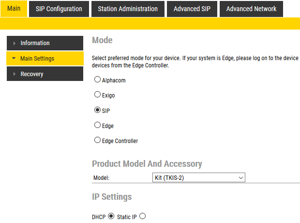
- Select Station Main > Main Settings
- Under Station Mode select Use SIP
- Under Product Model And Accessory select Kit
- Depending on system requirements, set the IP Settings to DHCP or Static IP. In the latter case, fill in the network details as required.
- Click Save
- On the new page, click Apply
The unit will now reboot.
Audio Settings
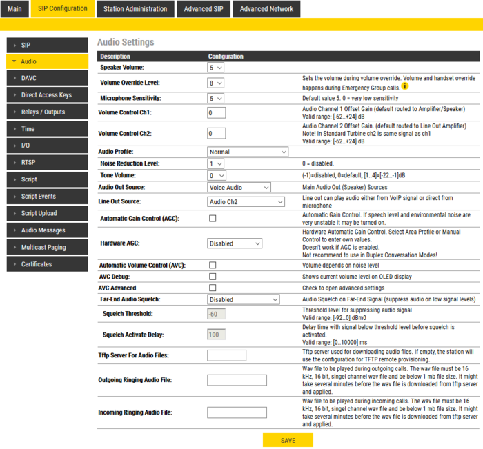
Normally no changes are required to be made to the audio settings, but depending on the specific circumstances where the unit is installed, minor adjustments may be needed.
- Select SIP Configuration > Audio Settings
On this page it is possible to set:
- Speaker Volume
- Microphone Sensitivity
- Noise Reduction Level
Furthermore, it is possible to select different algorithms for the Conversation Mode.
I/O Settings
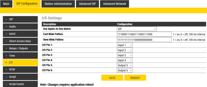
Select SIP Configuration > I/O Settings
Under Configuration set the following values for the I/O Pins:
- I/O Pin 1: Input 1
- I/O Pin 2: Input 2 or Output 2 – depending on the application for which this I/O will be used
- I/O Pin 3: Input 3 or Output 3 – depending on the application for which this I/O will be used
- I/O Pin 4: Input 4
- I/O Pin 5: Output 5
- I/O Pin 6: Output 6
Click Save
Although the ECP-AA1 will not use these settings until after a reboot, it is not necessary to reboot at this stage.
Output Settings
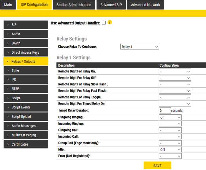
Select SIP Configuration > Relay Settings
CCTV Interface
For Choose Relay To Configure: Select Relay 1
Under Configuration set the following values:
- Outgoing Ringing: On
- Idle: Off
Click Save
General Settings
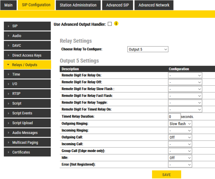
For Choose Relay To Configure: Select Output 5
Under Configuration set the following values:
- Outgoing Ringing: Slow flash
- Outgoing Call: Off
- Idle: Off
Click Save
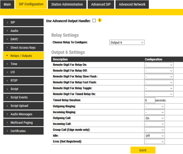
For Choose Relay To Configure: Select Output 6
Under Configuration set the following values:
- Outgoing Call: On
- Idle: Off
Click Save
Call Buttons
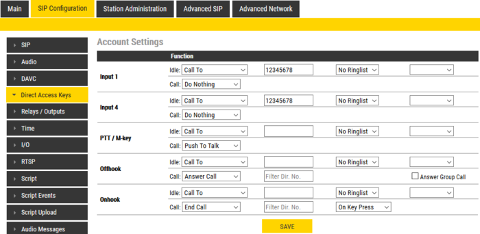
Both the call button on the unit and the emergency brake input are set up as a call button. Select SIP Configuration > Direct Access Key Settings
Assuming that the call button should call a fixed number:
- Enter the number to be called in the field Value for both Input 1 and Input 4
- Make certain that the Function (in call) settings for both inputs are set to Do Nothing
Click Save
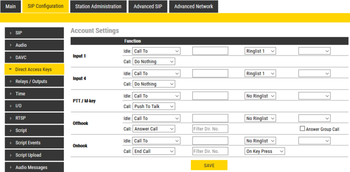
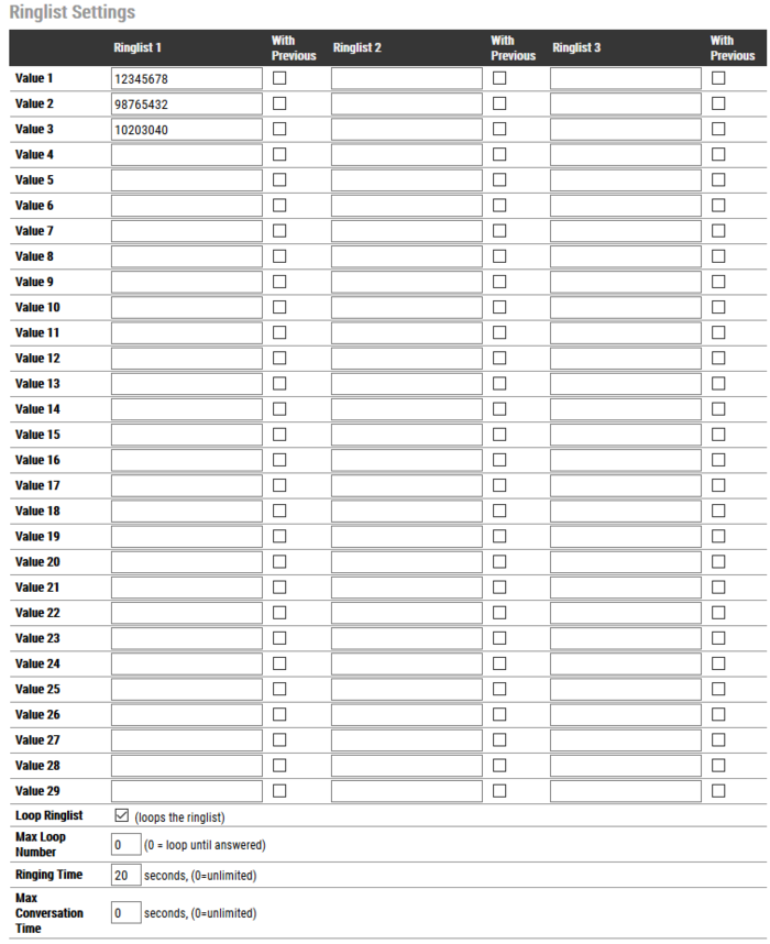
Ringlist Settings
Optionally it is possible to make the ECP-AA1 call numbers in sequence until the call is accepted. If this is the requirement, make the settings as shown below:
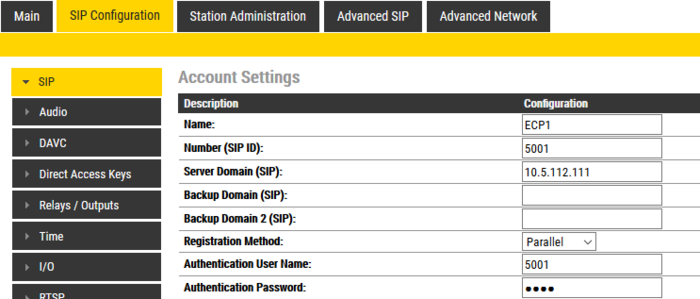
SIP Configuration
For the ECP-AA1 to be able to register to a SIP server, the correct SIP settings must first be done.
- Select SIP Configuration > SIP Settings
- Enter values for : Display Name, Directory Number (SIP ID), Server Domain (SIP), Authentication User Name
- Enter values in other fields as may be required by the SIP server
- Click Save
- Click Apply
The ECP-AA1 will now reboot and all settings that have been made in the previous sections will take effect when the unit is up and running again.

