AMAG Symmetry - ICX-AlphaCom integration
From Zenitel Wiki
Contents
- 1 General
- 2 Information from AMAG
- 3 Capabilities
- 4 Licensing
- 5 Introduction
- 6 Setting Up the System
- 6.1 Numbering Plan
- 6.2 AlphaPro Configuration
- 6.3 Web Configuration
- 6.4 Configuring the SMS Software
- 6.4.1 Step 1 – Add a License for Intercom Management
- 6.4.2 Step 2 – Configure a Client Port
- 6.4.3 Step 3 – Set Up a LAN Chain
- 6.4.4 Step 4 – Set Up the Intercom Client
- 6.4.5 Step 5 – Set Up Call Stations
- 6.4.6 Step 6 – Configure Intercom Groups
- 6.4.7 Step 7 – Set Up Alarm Reporting
- 6.4.8 Step 8 – Set Up Graphics
- 6.4.9 Step 9 – Set Up Trigger Commands
- 7 Using the System
- 8 Using ITSV-1 as operator station
General
The ICX or AlphaCom system communicate with AMAG Symmetry via the MPC-protocol.
AMAG is a brand/company name used in some countries, in other countries the company is known as G4S Technology or G4 Tec. Symmetry is also sold under the names Multimax, NSM or S8600.
Information from AMAG
- AMAG™ Access Control and Security Management System
- The Symmetry™ Intercom Control Integration package
- Video: Intelligent Communications with Zenitel
Capabilities
- When a call request is made video surveillance cameras can be moved to the callers location and automatically displayed to the Symmetry system operator
- Incoming intercom calls can be displayed on a graphical map along with all of the other elements of the integrated system to allow a single visual means of control
- Intercom stations can be linked through Symmetry to other nearby security assets allowing the Symmetry system operator to release a door, open a barrier or take any other required action very simply even on a very large system
- Incoming intercom calls can be treated as alarms where required in critical environments
- Initiated from Symmetry, recorded or live voice announcements can be made at call station locations and / or along fence-lines to either provide information or enhance the local security provision
Licensing
ICX-AlphaCom: When used with the ICX-AlphaCom, the following license is required in the ICX-AlphaCom in order to enable the MPC port:
- 1002602400 - ILI-IF Interface enabling
Symmetry:
- INTERCOM-KIT-V9 – Intercom license for Symmetry SMS v9. Only one per Symmetry SMS System required.
- VID-CAM-001-V9– Video Integration Licenses. One needed for each Camera. The Intercom Integration for IC-EDGE supports the automatic call up of up to four cameras per Substation. In order to associate a camera, the camera must be defined in Symmetry.

|
VID-CAM-001-V9 assumes a single camera, but there are larger camera bundles as well (such as VID-CAM-016-V9 for a block of 16 cameras) |
Introduction
Overview of Intercom Management
The SMS Intercom Management software provides an easy-to-use graphical interface for managing, answering and responding to calls from intercoms connected to ICX/AlphaCom intercom systems. The intercoms are normally sited outside the building, such as at doors, parking barriers and other entrances. Typically, the intercoms are used by visitors or other personnel to request entry.
The software is a fully-integrated component of the SMS software. It enables operators to respond to calls using the same user interface used to manage other forms of security, such as access control, intrusion and video monitoring. This enhances operator efficiency by avoiding the need to learn and operate different systems.
An ICX/AlphaCom intercom system can communicate with the SMS software via an RS232 serial connection or over an Ethernet LAN.
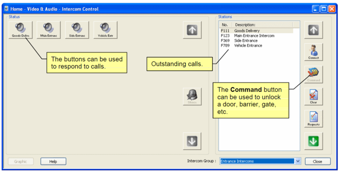
Calls (known as Call Requests) are answered and managed by from the "Home/Video & Audio/Intercom Control" screen (Figure 1). An incoming call is indicated by the appropriate intercom button flashing with a colored border, and by a sound, which can be different for each intercom. Clicking the intercom button opens an audio link between the operator's microphone and the person making the call.
The screen lists all outstanding call requests in a list box on the right-hand side of the screen. This allows the system to be used in busy environments where many incoming call requests may be made at the same time.
The integrated features of the software enable the operator to control other security devices while responding to a call. For example, when answering a call, the operator is able to unlock a door, barrier or other device by clicking the Command button.
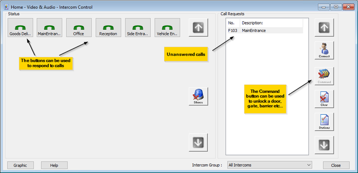
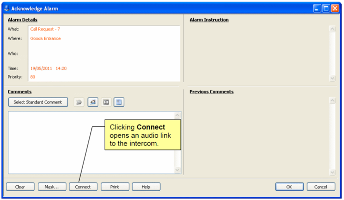
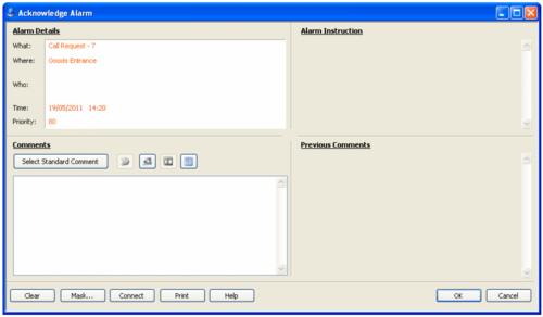
Operators can also view outstanding calls from the "Home/Monitoring/Alarms" screen (Figure 2), and respond to calls when acknowledging an alarm (Figure 3) or in the "Home/Monitoring/Graphics" screen (Figure 4).
Historical reporting of calls is fully integrated with the reporting features provided with the main SMS software. This allows reports of call activity to be included in reports of other security management activity.
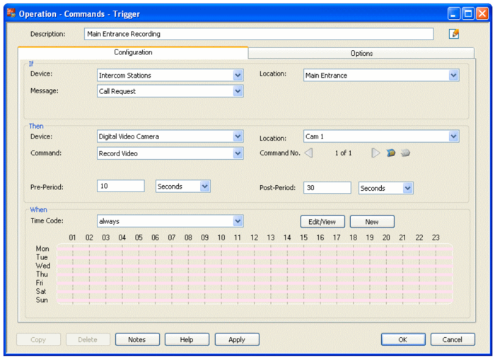
If required, trigger commands can be set up from the "Operation/Commands/Trigger" screen to operate security devices automatically when a call request is made. Trigger commands may, for example, be used to start a tagged CCTV recording. Figure 5 shows an example.
Benefits of the Interface
The SMS Intercom Management software provides many time-saving and security-enhancing benefits. Here are some examples:
- Standardized user interface – Call requests can be managed using the same SMS software that is used to manage other forms of security, such as access control, intrusion and video monitoring. This simplifies system operation, reduces training costs and improves efficiency.
- Integrated control of other SMS devices – In response to calls, operators are able to unlock doors and barriers or operate other security devices connected to the security management system.
- Automated control – Trigger commands can be set up to provide automatic responses to call requests. For example, a tagged CCTV recording could start when a call request is received.
- Standardized reporting – Call activity can be reported using the same screens and report layouts used for other security activity reporting.
- Easy management of busy sites – Multiple calls from different locations can be easily managed from a single screen. A dedicated Intercom Control screen displays and prioritizes all call requests.
- Call handling from Graphics – Operators can respond to calls from a plan, picture or map of the site.
- Multi-user capability – Call requests can be managed from any SMS client PC.
- Serial or LAN communications to SMS software – A serial or LAN link to an SMS client PC can be used.
Setting Up the System
Numbering Plan
AMAG uses the MPC Data Protocol, which has support for up to 4 digit numbering. When using 2 or 3 digit number plans, leading F's are required to comply with the fixed 4 digit Directory Number field in the MPC Data Protocol, i.e. FF10 or F101.
AlphaPro Configuration
Configuration of the system requires the AlphaPro software. The following description is for version 11.6; later versions may have a modified interface. You need to specify the settings that will enable the Zenitel system to communicate with the SMS Software.
Using the AlphaPro software:
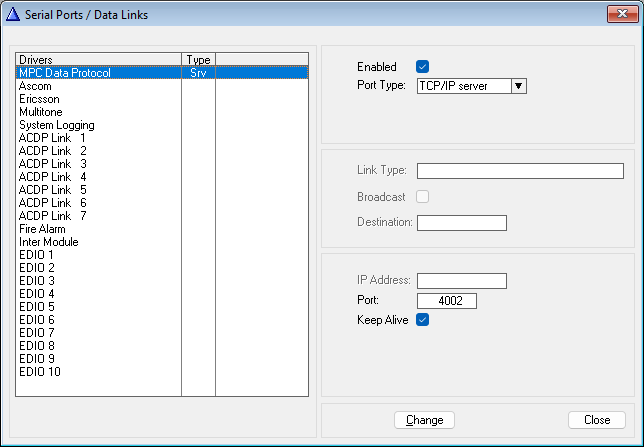
- Click the Exchange & System button in the main window.
- Click the Serial Ports button.
- Select the MPC Data Protocol from the list box.
- Set Port Type = TCP/IP Server, and Port = 4002
The settings above is used when the system connects to the SMS Software over a LAN. In this example TCP port number 4002 is used. Make a note of this number; you will need to enter it into the LAN Chain setup of the SMS software.
If you instead want to use serial RS232 link, set Port Type = "Serial 1".
Web Configuration
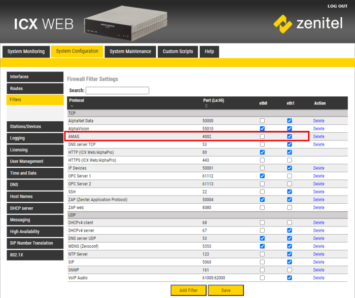
Log on to the web interface of the ICX-AlphaCom server, go to System Configuration > Filters:
- Select Add Filter, and define the same TCP port in the firewall (filters)
- Enable this TCP port on the relevant Ethernet port (Eth0 or Eth1)
Configuring the SMS Software
Configure the SMS software using the following steps.
Step 1 – Add a License for Intercom Management
Add a license for Intercom Management using the "Maintenance/System Licenses" screen.
Step 2 – Configure a Client Port
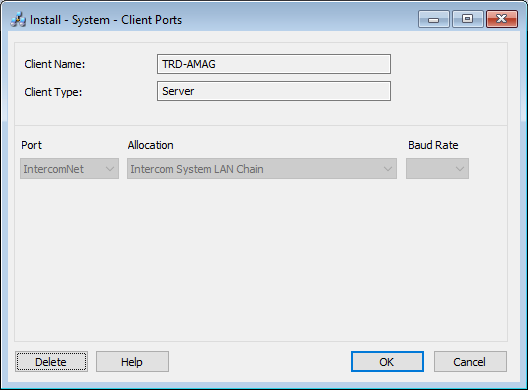
Open the "Install/System/Client Ports" screen in the SMS Software and specify the following:
- In the Selection screen, select the SMS client that is to communicate with the Zenitel system and click New. If you are using a serial link, this must be the client that the Zenitel system is physically connected to. If a LAN link is used, choose the SMS client that you want to manage communications.
- In the Definition screen, choose the Port and Allocation:
If a LAN link is used, select IntercomNET in the Port menu, and Intercom System LAN Chain in the Allocation menu. If a serial link is used, specify the COM port that the Zenitel system is connected to in the Port menu, and choose Intercom System in the Allocation menu. There can be only one intercom system per SMS installation.
Step 3 – Set Up a LAN Chain
If a LAN link is used between the Zenitel system and the SMS Software, open the "Install/Access Control/Chains/LAN" screen and set up a LAN chain.
Select the client and the LAN Port Name of IntercomNET. Specify the static IP address of the Zenitel system, and the Port Number, as specified when setting up the communication settings in AlphaPro.
Step 4 – Set Up the Intercom Client
Use the "Install/Video & Audio/Intercom/Clients" screen to specify the client PCs that will be used to answer call requests when using the "Home/Video & Audio/Intercom Control" screen, "Home/Monitoring/Graphics" screen or when acknowledging an alarm. Each client must be sited next to an intercom to enable the user to communicate with callers.
In Station Number, enter the number known to the intercom control unit that identifies the intercom being used at the client. Each intercom port on the Zenitel system has a station number. Ensure you add leading F's to the number to the required 4 digits. Select Show as a Call Station if you want other intercom clients to make calls to this client, or if you want to set up trigger commands triggered by calls from this client. A button will appear for the client's intercom in the "Home/Video & Audio/Intercom Control" screen, and you will be able to add the client's intercom to graphics.
Step 5 – Set Up Call Stations
Use the "Install/Video & Audio/Intercom/Call Stations" screen to specify the intercoms that are being used by visitors or other personnel. Typically, these are located at entrances, delivery points, parking barriers, etc.
Accept All Call Requests and Call Request ID
When a call request is made from an intercom, the intercom sends a Call Request ID. The intercom may have been set up to provide a specific ID, or the ID may be dependent on the button pushed. If you want to accept only calls that have a specific Call Request ID, deselect Accept All Call Requests and enter the ID in the field. All other call requests will be ignored.
Tip: The Call Request ID of an intercom can be determined from the status information in the "Home/Monitoring/Command Center" screen.
Command
This enables you to associate a command with the intercom. The command is issued by clicking the Command button in the "Home/Video & Audio/Intercom Control" screen after answering a call request from the intercom, or by right-clicking on an intercom in a graphic and selecting Command.
There are two types of command:
- Pulse output - Switches on the auxiliary output selected in the menu to the right for a predefined period of time (as specified by the installer), then switches it off.
- Grant Access - Performs the same action as a valid access-control transaction at the reader selected in the menu to the right (i.e. opens the door at the specified reader).
Associated Sound
If required, use the Browse button to select a sound (.wav) file for the intercom. The sound will be generated when a call request is received in the View/Intercom Control screen.
Step 6 – Configure Intercom Groups
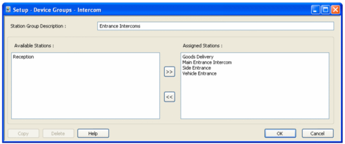
You can define groups of intercoms in the "Setup/Device Groups/Intercom" screen. The groups can be used in the "Home/Video & Audio/Intercom Control" screen to display intercom buttons for only those intercoms in a selected group. The groups can also be used for History Activity reporting ("Reports/History/Activity" or "Reports/Configuration/Predefined Reports/Predefined Activity" screen) to report alarms/events from only those intercoms in a selected group.
Step 7 – Set Up Alarm Reporting
If you want to be able to connect to intercoms when acknowledging alarms (page 17), use the "Operation/Alarms/Reporting" screen to specify the Call Request message as an alarm, and set up appropriate alarm routing in the "Operation/Alarms/Routing" screen.
Step 8 – Set Up Graphics
If you want to be able to connect to intercoms from graphics, use "Setup/Graphics/Add" and "Setup/Graphics/Setup" to set up the graphics.
Step 9 – Set Up Trigger Commands
You can use the "Operation/Commands/Trigger" screen to set up commands that are triggered by calls from intercom stations. This may be useful if, for example, you want to start a recording when a call request button is pressed.
Using the System
Using the Intercom Control Screen
The "Home/Video & Audio/Intercom Control" screen is used to answer call requests. A call request is started when a call request button is pressed at an intercom, typically by visitors or other personnel who require access to the building. After speaking with the caller, you can press a Command button, which can perform an action such as opening a door or barrier.
The screen can also be used to speak with people at other intercoms around the building, even if no call request has been received.
The following illustration shows the key features of the Intercom Control screen.
Receiving Call Requests
When a call request is received from an intercom, it is listed in the Requests area on the right of the screen, and the corresponding button changes to the following with a flashing pale blue border:
The Requests area can list multiple call requests. The call requests are listed in order of receipt, with the oldest at the top. Arrow buttons are provided for scrolling up/down the list. Each intercom can be associated with a different sound, and the sound played is always the one associated with the call request at the top of the list.
If you minimize the "Home/Video & Audio/Intercom Control" screen, the screen is maximized automatically when a new call request is received.
Answering Call Requests
When a call request is received, you can choose to open a line between the intercom located at your PC and the intercom from which the call request was made.
You can answer a call request as follows:
1. Press the intercom button (with the pale blue border), or select the call request from the Requests list and click the Connect button. Clicking Connect without selecting a call request connects to the first in the list. It is not possible for more than one user to connect to the same intercom at the same time.
2. If you have to wait to connect to the intercom (e.g. because a handset has to be picked up at the intercom), you will see the button change to the following (olive border):
3. When a successful connection is made, the button changes to the following (orange border):
4. Speak with the person at the intercom.
5. If the intercom has been associated with a command (in the "Install/Video & Audio/Intercom/Call Stations" screen), the Command button is enabled. Pressing the button sends the command. Typically, the command is used to open a door or barrier for the caller.
6. When you want to terminate the conversation, click the button shown above or choose Connect again. The call request is removed from the list, and the button changes to display the default icon.
Calling Other Intercoms
You can open a line to any intercom simply by clicking on the button associated with the intercom you want to connect to, even if no call request has been received. Once a successful connection is made, the button of the intercom you are using (if shown) is displayed as follows and the one you are connecting to is displayed with an orange border.
If the intercom has been associated with a command, the Command button is enabled while you are connected to it.
You can terminate the call simply by clicking the button again (or another button).
Note: Any two intercoms currently communicating are indicated with the above button icon. This enables you to determine which intercoms are currently in use.
Answering Calls from the Acknowledge Alarm Screen
The Connect button is displayed when acknowledging an alarm if an intercom has generated a Call Request alarm. You can use Connect to start an audio link between your intercom and the intercom making the call request.
When you click Connect, the button name changes to Disconnect, which allows you to disconnect the link. The link is automatically disconnected when you close the Acknowledge Alarm screen.
Answering Calls Requests from the Graphics Screen
You can also answer call requests from the "Home/Monitoring/Graphics" screen if intercoms have been added to graphics in the "Setup/Graphics/Setup" screen. The following icon is used:
The border of the icon flashes in pale blue when a call request is received. Right-clicking the icon and selecting Connect opens the audio link to the intercom and the color changes to orange (flashing).
History Reporting
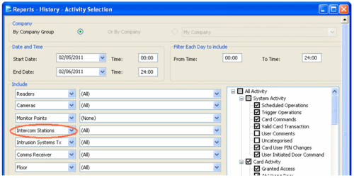
The "Reports/History/Activity" screen can be used to produce reports of intercom call requests and other intercom alarms and events:
You can choose to report on Intercom Stations or Intercom Groups.
Choose All if you want to include the alarms and events, no matter which intercom they relate to.
Choose an intercom or group if you want to include alarms and events only if they have been produced from the specified intercom or an intercom in the group.
Using ITSV-1 as operator station
The ITSV-1 is a Vingtor-Zenitel SIP telephone. To be able to use it as an operator intercom, the following setting must be made:
- Log in into the ITSV-1 web page (default credentials: admin/alphaadmin)
- Navigate to Call Settings related to the account that is used to connect to the ICX or AlphaCom.
- Make the setting as indicated in the picture below
The use of an ITSV-1 as operator station is supported as from AMC-IP software version 13.1.3.3 and IXC software version 1.0.3.2. Using the ITSV-1 as operator station works best if calls to Ringing Groups are used instead of call requests.
- Add all operators (even if there is only 1 operator) as member in a Ringing Group - By default Groups 51-60 are setup as Ringing Group in ICX and AlphaCom
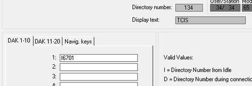
- Program the call buttons of sub-stations to make a call to a Ringing Group - for instance, use I 6701 to make a call to all operators in the first Ringing Group, group 51


