DCB
From Zenitel Wiki
Contents
- 1 Introduction
- 2 Equipment
- 3 Installation
- 3.1 Installation Overview
- 3.2 Planning the installation
- 3.3 Transferring Customer Data from PMC/PMF to PMFR
- 3.4 Installing ABD2/ABD Boards
- 3.5 Plugging in the Display Stations
- 3.6 Basic Test of Display Stations
- 3.7 Installing the DCB Board 1000638740
- 3.8 Connectiong the Data Terminal to the DCB Board
- 3.9 LED Behaviour
- 4 Programming
- 4.1 Programming Overview
- 4.2 Exchange Programming (use the Programming Panel)
- 4.3 Programming the DCB Board (use the Programming Panel)
- 4.4 System Setup (use the Terminal)
- 4.5 Identifying the Display Stations
- 4.6 General Display Layout
- 4.7 Numbers for the "Directory" and "Info" Feature
- 4.8 Commands Used for Service And Customizing
- 5 Upgrading / Customizing
- 6 Troubleshooting
Introduction
Guide to Reader
This manual provides information on the complete procedure for the installation and commissioning of the Stentofon TouchLine Display System.
The manual deals with the installation and commissioning of Display System only, and not the standard installation and commissioning of the TouchLine exchange (refer to the standard "Installation & Commissioning Manual" for TouchLine exchanges).
The manual shows how to add the Display System to an existing TouchLine System. It is divided into the following parts:
- A short description of the necessary equipment
- Installation
- Programming
- Upgrading (to DCB 03.00/Customizing
- Troubleshooting
- Appendixes
In the Appendixes you will find the necessary cable drawings, technincal specifications, additional programming information, information on connection and set-up of terminals, schematics, and the stanard screen/display texts.
General Description of the STENTOFON TouchLine Display System
The Display System requires the following equipment:
- Display Stations
- ABD2/ABD Board (Subscriber Board with data transmission)
- PMFR board (or PMF with software version 01.30)
- DCB Board (Display Controller Board)
- Data Terminal (to program the DCB Board)
The Display System provides a great number of useful display features for the Stentofon intercom user.
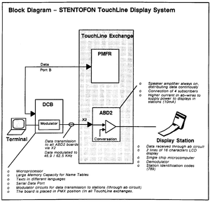
The following paragraphs gives a brief electrical description with a Block Diagram of the Stentofon TouchLine Display System:
- The PMFR board continously reports the status of all stations in the system through Port B (standard exchange output)
- The DCB board identifies the status of each station and serially transmits appropriate display infromation
- The serial display information is modulated. The data is transmitted together with audio to oudspeaker through the a/b circuit
- The Display Station provides a demodulator and microprocessor which receives data and controls the display
The Reader
This manual is aimed at personnel who have earlier installed TouchLine Exchanges, and people trained at STENTOFON's installation courses.
Limitations
Maximum Number of Display Stations when using ABD boards 1000610110
Due to the high power consumption when using Display Stations, the number of Display Stations connected to each exchange is limited to 75% of the total number of subscriber boards when ABD boards are used. The limitation concerns all exchanges, except for Exchange 52/8.
The table shows the maximum number of ABD boards 1000610110 and Display Stations which can be used in different exchange sizes. As a general rule, a maximum of 15 ABD boards can be installed in each BWAP Module.
NOTE:
- When using ABD2 boards 1000610120 each BWAP module may be fully equipped with 20 ABD2 boards.
| Exchange Size | Max. No. of ABD Boards | Max. No. of Display Stations* |
|---|---|---|
| 52/8 | 13 | 50 |
| 120/12 | 22 | 86 |
| 160/22 | 30 | 118 |
| 240/22 | 45 | 178 |
| 320/22 | 60 | 238 |
| 400/22 | 75 | 298 |
| 480/22 | 90 | 358 |
| 560/22 | 105 | 418 |
| 640/22 | 120 | 478 |
| 720/22 | 135 | 538 |
| 800/22 | 150 | 598 |
| 880/22 | 165 | 658 |
| 960/22 | 180 | 718 |
| 1040/22 | 195 | 778 |
- The GCP Board and the Programming Panel each require 1 subscriber line.
Maximum Loop Resistance
The maximum loop resistance is 120 Ohm for ABD boards, and 240 Ohm for ABD2. The distance between the exchange and Display Stations must not exceed the following distances:
- When using ABD boards 1000610110:
- 1000 meters (approx. 3000 ft.) when using 0,6 mm cable.
- 1700 meters (approx. 5100 ft.) when using 0,8 mm cable.
- When using ABD2 boards 1000610120:
- 2000 meters (approx. 6000 ft.) when using 0,6 mm cable.
- 3400 meters (approx. 10200 ft.) when using 0,8 mm cable.
Related Documentation
| Title: | Item No.' |
|---|---|
| "Installation & Commissioning", Exchanges 52 & 120 | IM1559 |
| "Installation Instructions", Exchanges 160 to 1040 | IM1543 |
| "Programming Journal", TouchLine System | SI1429 |
| "Programming Guide", TouchLine System | SI1428 |
| "Supplement to Programming Guide", PMFR 03.30 | SI1661 |
| "Installation Instruction", PMFR Board | IM1567 |
| "Installation Instructions", SB4 Board | IM1558 |
Notation
Throughout the manual you will find different notations. The purpose of using notations is to make it easier for the reader to distinguish between instructions, additional information, very important information etc.
The following notations are used:
- ●
- ▬
- ►
- NOTE!
- WARNING!
Equipment
Equipment List
The STENTOFON TuchLine Display System requires microprocessor board PMFR 1000631690 (or PMF 1000631600 with software 01.30). In addition to the standard exchange equipment, the following is required:
- Diaply Stations
- ABD2 Boards 1000610120/ABD Boards 1000610110 - (Subscriber Boards with data transmission)
- 1 DCB Board 1000638740 (Display controller Board)*
- Data Terminal (required when programming the DCB board)
In newer exchenges the necessary Display Data Cables are ready installed. When updating "older" exchanges, these cables must be connected to the back-wiring of the exchange during installation (see subsection 3.7.1).
- An additional cable for communication between the PMFR board and the DCB board is delivered with the DCB board.
Display Stations
The Display Station operates the same way as standard stations, but has a display (LCD) with two lines of 16 characters. The display gives information on intercom features and other helpful information. It also tells the user what to do when accessing features (menu/help) and it provides a "Directory" and "Info" list. The station is also equipped with 10 Single Touch keys (DAK).
- Display Station 10070013xx, desk station with handset
- Display Station 10070023xx, desk station without handset
- Display Station 10070343xx, wall station with handset
- Display Station 10070363xx, wall station without handset
Subscriber Board ABD 1000610110/ABD2 1000610120
Each board contains individual subscriber circuits for four subscribers. The board is equipped with input and ouptput amplifiers. It provides circuits for remote control features and a data channel for data transmission to Display Stations. It is required when using Display stations. The boards can also be used for standard stations.
ABD2 boards are improved compared to ABD boards, as described in Section 1.4. We recommend that ABD2 boards are used.
The Boards fit into AB positions in the modules BWAP, BWCPR or BWSPR.
Microprocessor Board PMFR 1000631690
The Microprocessor on this board controls all functions of the exchange in accordance with a stored program. The PMFR boards has an expanded memory capacity compared to PMF. (PMF with software 1.3 can also be used). One board is required in each exchange.
The PMFR board fits into the PMC/PMF position in the modules BWCPR, BWSPR, BWFP or BWBP.
Display Controller Board DCB 1000638740
This board has standard display software, and is required when using Display Stations. The board provides a modulator circuit which enables data transmission to the Display Stations through the loudspeaker (a/b) circuit. One board is required in each exchange.
The DCB board fits into the PMX position in all exchanges in the modules BWCPR, BWSPR, BWFP or BQBP.
Data Terminal
When programming the TouchLine Display System (the DCB board), a data terminal is required. The data terminal must provide an RS-232 or RS-422 port interface. In Appendix H you will find information on terminal types and set-up standards.
Installation
Installation Overview
This section shows how to prepare and install the necessary equipment when adding a Display System to an existing TouchLione System.
The installation consists of the following step:
- Planning the installation
- Transferring Customer Data from PMC/PMF to PMFR (if necessary)
- Installing ABD2 boards or ABD boards
- Plugging in Display Stations
- Executing the Basic Test for Display Stations (as for standard stations)
- Installing the DCB board
- Installing the Display Data Cables
- Cable connection between the PMFR board and the DCB board
- Connectiong a data terminal to the DCB board
Planning the installation
Display Stations can be used together with other standard stations in the same exchange, but Display Stations must be connected to an ABD2 or ABD board. Each board contains circuitry for 4 stations, which either can be Display Stations or tandard sations.
The board must have the correct switch settings according to the type of stations that are connected to the corresponding Physical Positions. Both boards provide a 4-pole dip-switch. Each switch refers to a physical position.
- ► First, always decide which physical positions in your exchange are to be prepared for Display Stations. Make a note (for example "DS") for each of these Physical Positions in the column for "Special Notes" in the "Programming Journal".
- ► If ABD boards are used, remember the limitations, section 1.4.
Your starting point determines how the installation and commissioning of the STENTOFON TouchLine Display System is executed:
- ► If you are going to update an existing TouchLine System, proceed through this manual section by section.
- ► If you are going to carry out an installation and commissioning of a complete STENTOFON TouchLine Display System from scratch, refer to standard "Installation & Commissioning" instructions for TouchLine exchenges.
- Remember that the PMFR bord (or PMF with software version 01.30) must be installed during the standard installation and commissioning. Install all board, except for ABD2/ABD boards which are installed at a later point.
- When the standard installation and commissioning is completed, continue by following all procedures in this manual, except for subsection 3.3, "Transferring Customer Data from PMC/PMF to PMFR".
Transferring Customer Data from PMC/PMF to PMFR
The STENTOFON TouchLine Display System requires the microprocessor board PMFR 1000631690 (orPMF with software version 01.30). If the existing exchange is equipped with PMC or PMF board, customer data must be transferred from the PMC/PMF board to the PMFR board.
- ► Skip this subsection and go to the next (3.4) if this is an installation and commissioning of the complete STENTOFON TouchLine Display System from scratch.
Depending on what kind of microprocessor board your exchange is equipped with, transfer data by doing one of the two following operations:
- 1) When replacing PMC or PMF without EEPROM back-up with PMFR, normal tape back-up procedures must be used to transfer customer data from PMC to PMFR.
- First, dump the customer data from the PMC board onto a tape.
- Verify the tape content by running a verify sequence.
- Load the customer data from the tape onto the PMFR board.
- Verify the loading.
- A detailed description of this procedure is included in the "Installation Manual"" and "Programming Guide" for TouchLine exchanges.
- 2) When replacing PMF board 1000631600 (EEPROM back-up for customer data) with PMFR, the following procedure is required:
- If your EEPROM back-up has to be updated:
- Prepare the existing PMF board for dumping. Insert the EEPROM's and set the dip-switches in the correct standard position according to the type of EEPROM which is used.
- Dump the program (from the Programming Panel: Dial E25 + EEEE + ACT).
- Insert the EEPROMs on the PMFR board.
- Load with E26.
- If your EEPROM back-up is updated:
- Insert the EEPROMs on the PMFR board.
- Load with E26.
A detailed description of this procedure is included in the "Installation Instructions" for the PMFR board, IM-1567.
Installing ABD2/ABD Boards
ABD2 Boards
Each module may be fully equipped with ABD2 boards (maximum 20 ABD2 boards in a BWAP module).
ABD Boards
If ABD boards are used, remember the maximum number of ABD boards in an exchange, refer to the table in section 1.4.1.
Board Position
The following modules provide AB positions for ABD2/BAD boards (or AB boards):
- BWAP module
- BWCPR module
- BWSPR module
Switch Settings
Each ABD2/ABD board must have the correct switch settings according to the type of stations that are connected. There are 4 dip-switches, each one referring to a physical position.
- For ABD2 boards:
- Switch 4 refers to the uppermost Physical Position on the backwiring - switch 1 to the lowest Physical Position.
- for ABD boards:
- Switch 1 refers to the uppermost Physical Position on the backwiring - switch 4 to the lowest Physical Position.
- ► A Physical Position is prepared for a Display Station when the corresponding switch is in ON position.
- ► A Physical Position is prepared for a standard station when the corresponding switch is in OFF position.
The following example shows how to set the switches when two Display Stations and two standard stations are connected to Physical Positions in an AB position (Physical Position 50, 51, 52 and 53):
- Settings on ABD2:
| Position: | Switch | ON/OFF |
|---|---|---|
| 50 | 4 | ON |
| 51 | 3 | ON |
| 52 | 2 | OFF |
| 53 | 1 | OFF |
- Settings on ABD:
| Position: | Switch | ON/OFF |
|---|---|---|
| 50 | 1 | ON |
| 51 | 2 | ON |
| 52 | 3 | OFF |
| 53 | 4 | OFF |
- ● Set the correct switch settings according to the notes you have made in the column for "Special Notes" in the "Programming Journal".
Inserting the board
- NOTE!
- Before inserting or removing any of the printed circuit boards, make sure that the mains power is OFF.
- Be aware of static electricity.
- Set the correct switch settings according to the notes you have made in the column for "Special Notes" in the "Programming Journal".
- Insert the boards in the selected AB positions in the exchange.
- ► The boards are testet by establishing connection to all Display Stations to the boards (refer to subsection 3.6).
Plugging in the Display Stations
Your TouchLine Exchange is now installed, programmed and testet according to standard "Installation & commissioning" instructions for TouchLine Exchanges. All necessary boards, including the ABD2/ABD boards.
- ● Plug the Display Stations in the correct wall sockets according to the plan you have made in the "Programming Journal".
- ► Remember, the corresponding Physical Positions must be prepared for Display Stations!.
- ► At this point the Display Stations are installed for the Basic Test of standard intercom features, not Display Features.
Basic Test of Display Stations
The following procedure describe the basic test of standard intercom features for the Display Stations. During the test, connection is established to all Display Stations. In this way, the ABD2/ABD boards are also tested, except for display features. The test procedure may vary a bit depending on the type and size of the exchange which is installed. The following instructions describe therefore the test in general:
- Set up conversation between the two stations by dialling from A to B, and then from B to A.
- - Test the voice switching (Duplex) and the manual switching (Simplex).
- - Test the cancelling from either side and the "Do not Disturb" (Private/Open) features.
- Check the following points on all the Display Stations:
- - The keyboard 0-9
- - The volume control
- - The PRIVATE/OPEN switch
- - The M-key
- - The C-key
- - The Display Station's own number
- ► The station verifies the correct number by responding with a rapid "attention" tone (-very rapid pulses for four seconds, followed by a normal, muted busy tone).
- Continue connecting the remaining Display Stations, one at a time. Repeat the test procedures for each new Display Station (for example, set up conversation between two stations by dialling from C to B, and then from B to C, and so on).
- If faults appear, refer to Faultfinding Procedures in the standard "Installation & Commissioning" instructions for your exchange.
- ► For detailed information on test procedures, refer to standard "Installation & Commissioning" instructions for TouchLine Excheanges.
Installing the DCB Board 1000638740
Installing the Display Data Cables
In exchanges made in 1991 or later, the Display Data cables are ready installed. However, in larger exchanges (larger than 240) the cables must be interconnected between the different cabinets. Each cable is equipped with a female or male snap-on plug for the interconnection between cabinets.
When updating "older" exchanges the Display Data Cables must be connected to the back-wiring of the exchange during installation. A cable set is available from your STENTOFON dealer. Depending on the exchange size the cable set has one of the following item numbers:
| Exchange Size: | Item No. Cabinet(s) | Item No. Cable Set |
|---|---|---|
| 160/22 | 1000636800 | A100B09052 |
| 160/22-240/22 | 1000636300 | A100B09047 |
| 320/22-480/22 | 1000636500 / 1000636600 | A100B09049 / A100B09050 |
| 560/22-800/22 | 1000636500 / 1000636600 / 1000636700 | A100B09049 / A100B09050 / A100B09051 |
| 880/22-1040/22 | 1000636500 / 1000636600 / 1000636700 / 1000636700(-S) | A100B09049 / A100B09050 / A100B09051 / A100B09051 |
In Appendixes A-E you will find the complete drawings of Display Data Cables for all exchanges sizes
Cable Connection Between the PMFR Board and the DCB Board
The cable is connected to the back-wiring between the position for the PMFR board (PMC position) and the position for the DCB board (Position PMX2) in the modules BWFP, BWBP, BWCPR or BWSPR.
The cable is delivered together with the DCB board.
- ● Consult the drawing and connect the cable.
Board Position
Any PMX position can be used, but it is recommended that the DCB board is inserted in the PMX2 position in TouchLine exchanges:
Exchange 52/8           BWCPR module
Exchange 120/12         BWSPR module
Exchange 160/22         BWFP module
Exchange 160-240/22     BWBP module
Exchange 320-1040/22    BWFP module
Switch Settings
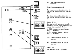
The DCB board is delivered from the factory with standard switch settings.
- ● First, verify that the board has the standard switch settings.
When preparing the DCB board, pay special attention to dip-switch S15-5. This dip-switch must be set according to the terminal type which is used.
- ● Prepare the DCB board as shown on the drawing:
Inserting the Board
- NOTE!
- Before inserting or removing any of the printed circuit boards, make sure that the mains power is OFF.
- Be aware of static electricity.
WARNING!

Risk of fire, expolision and burns!
The DCB Board is equipped with a LITHIUM Battery ER6/3.6V.
Avoid short circuiting the battery.
Do not recharge the battery.
Do not dissemble or incinerate the battery.
Do not expose the battery to heat above 85°C.
- ● Insert the DCB board in the PMX2 position in your exchange.
- ► PMX2 position is recommended. If you already have an additional feature board in this position, the PMX1 position can be used. Make sure that the Display Data Cable, the cable between PMFR/DCB and the Terminal Cable on the back-wiring is connected to the corresponding PMX position.
Connectiong the Data Terminal to the DCB Board
In order to program the DCB board, a terminal is required. The data terminal must provide an RS-232 or RS-422 interface. Remember that switch S15-5 on the DCB board must be set according to the type of terminal which is used (Section 3.7.4). For further information on terminal types, refer to Appendix H, "Connection and Set-up of Terminals".
If the terminal has an RS-232 interface, the terminal must be connected to the RS-232 input port on the DCB board (position PMX2), i.e. side A.
If the terminal has an RS-422 interface, the terminal must be connected to the RS-422 input port on the DCB board (position PMX2), i.e. side B.
- ● Consult the drawing and connect the terminal to the TouchLine exchange.
LED Behaviour
There are 3 different LEDs on the DCB board (RUN, IDLE and STATUS), situated on the upper right corner:
RUN - This LED is lit (steady light) during normal operation.
A blinking LED indicates that the processor is not running due to some hardware error, or a software configuration problem.
IDLE - This LED is off when the processor is not working. The LED lights up when the processor is working (transmitting/receiving data).
STATUS - This LED is mostly off (it flickers randomly) during normal operation.
When the DCB board is in programming mode (the green button is pressed quickly), the LED blinks with a fixed frequency of approximately 0,5 Hz.
Neither the displays nor the terminal will work when the DCB board is in this mode.
Programming
Programming Overview
If you are only going to upgrade your system to software version DCB 03.00, go straight to Section 5; "Upgrading/Customizing".
If you are going to program the STENTOFON TouchLine Display System the very first time, the following procedures must be performed:
- Exchange Programming (section 4.2)
- Step 1: Programming Directory Numbers to be used for "Info" and "Directory" Feature.
- Step 2: Setting Reference Information for the Directory Numbers.
- Step 3: Setting Baud Rate for Data Communication. (Not required for PMFR 03.30 or later.)
- Programming the DCB Board (section 4.3)
- Step 1: Creating Board Adress Before Cold Start.
- Step 2: System Cold Start.
- System Setup (section 4.4)
- Step 1: Create EEPROM Back-Up (command 8).
- Step 2: Set System Clock (command 3).
- Step 3: Change Password (command 7).
- Step 4: Enter Subscriber Name and Information (command 1).
- Identifying the Display Station (section 4.6)
Section 4.5 describes the commands used for service and customizing.
Appendix G provides the following additional programming information:
- Configuration Tables
- - Adressing the DCB oard
- - Exchange Communication Table
- - Serial Port Tables
- LCD Display Configuration
- - Function Selection
- - Display Related Intercom Numbers
- - Menus Describing Extra Action Digits
- - Terminal Operations Values
- - Screen and Text Layouts
- TouchLine (MPC) Tabel Programming
- - Directory Numbers
- - Configuration Bits
Exchange Programming (use the Programming Panel)
Step 1: Programming Directory Numbers to be used for "Info" and "Directory" Feature
| Text: | Programming | Observe Display |
|---|---|---|
| Enter the dummy number table | ► Press E51 | A:0051 B:0004 C:All off |
| Find a free line (In this example 92 is used) | ► Press 0092 | A:0092 B:0000 C:All off |
| Display directory number | ► Press READ | A:0092 B:FFFF C:All off |
| Enter Directory number to be used for display activation | ► Press F789 | A:0092 B:F789 C:All off |
| Activate programming | ► Press ACTIVATE | A:0092 B:F789 C:All off |
| Go to the next free line (example: line 93) | ► Press STEP | A:0093 B:FFFF C:All off |
| Enter Directory Number to be used for "Info" Feature (accessed from D10) | ► Press 7891 | A:0093 B:7891 C:All off |
| Activate programming | ► Press ACTIVATE | A:0093 B:7891 C:All off |
| Go to the next free line (example: 94) | ► Press STEP | A:0094 B:FFFF C:All off |
| Enter Directory number to be used for "Directory" Feature (accessed from D10) | ► Press 7892 | A:0094 B:7892 C:All off |
| Activate programming | ► Press ACTIVATE | A:0094 B:7892 C:All off |
| Leave programming mode | ► Press CANCEL | A:0094 B:7892 C:All off |
<br\> Step 2: Setting Reference Information For the Directory Numbers
| Text: | Programming | Observe Display |
|---|---|---|
| Enter table for ref info of dummy numbers | ► Press E52 | A:0052 B:0001 C:All off |
| Enter Directory Number | ► Press F789 | A:F789 B:0000 C:All off |
| Display current ref info for this Directory Number | ► Press READ | A:F789 B:0092 C:All on |
| Press the extended Keyboard until display C is as shown | ► Program ref info | A:0092 B:F789 C:0-8 on |
| Activate programming | ► Press ACTIVATE | A:F789 B:0092 C:0-8 on |
| Reset for next programming | ► Press CLEAR | A:0052 B:0001 C:All off |
| Enter Directory Number | ► Press 7891 | A:7891 B:0000 C:All off |
| Display current ref info for this Directory Number | ► Press READ | A:7891 B:0093 C:All on |
| Press the extended Keyboard until display C is as shown | ► Program ref info | A:7891 B:0093 C:0-8 on |
| Activate programming | ► Press ACTIVATE | A:7891 B:0093 C:0-8 on |
| Reset for next programming | ► Press CLEAR | A:0052 B:0001 C:All off |
| Enter Directory Number | ► Press 7892 | A:7892 B:0000 C:All off |
| Display current ref info for this Directory Number | ► Press READ | A:7892 B:0094 C:All on |
| Press the extended Keyboard until display C is as shown | ► Program ref info | A:7892 B:0094 C:0-8 on |
| Activate programming | ► Press ACTIVATE | A:7892 B:0094 C:0-8 on |
| Leave programming mode | ► Press CANCEL | A:7892 B:0094 C:0-8 on |
<br\> Step 3: Setting Baud Rate for Data Communication (not required on PMFR 03.30 or later)
| Text: | Programming | Observe Display |
|---|---|---|
| Enter System Constants Table | ► Press E54 | A:0054 B:0004 C:All off |
| Go to line 18 | ► Press 0018 | A:0018 B:0000 C:All off |
| Display current ref info | ► Press READ | A:0018 B:00d0 C:All off |
| Enter baudrate for data communication (0034=9600 Baud) | ► Press 0034 | A:0018 B:0034 C:All off |
| Activate programming | ► Press ACTIVATE | A:0018 B:0034 C:All off |
| Go to line 19 | ► Press STEP | A:0019 B:00d0 C:All off |
| Enter baudrate for data communication | ► Press 0034 | A:0034 B:0034 C:All off |
| Activate programming | ► Press ACTIVATE | A:0019 B:0034 C:All off |
| Leave programming mode | ► Press CANCEL | A:0019 B:0034 C:All off |
<br\>
- ● When the programming is completed, press the red reset button on the PMFR board.
Programming the DCB Board (use the Programming Panel)
NOTE!
If you have a DPB (Data Processing Board) in the exchange, make sure that this board is not in programming mode before you set the DCB board
in programming mode and execute Step 1 and Step 2.
<br\>
- ● Set the DCB Board in Programming Mode by pressing the green button quickly. The lowest LED starts flashing.
<br\> Step 1: Creating Board Adress Before Cold Start
| Text: | Programming | Observe Display |
|---|---|---|
| Enter OpCode | ► Press E62 | A:0062 B:0005 C:All off |
| Enter adress 0100 | ► Press 0100 | A:0100 B:0000 C:All off |
| Read info | ► Press READ | A:0100 B:0000 C:All off |
| Enter device identification (Recommended value is DCB0, which is displayed on the 7-segment display as "dCb0")* | ► Press DCB0 | A:0100 B:dCb0 C:All off |
| Activate programming | ► Press ACTIVATE | A:A300 B:dCb0 C:0,1,3,4,5,8,A,B on |
*) Applies to addressing DCB boards in linked exchanges:
The last digit in the adress must correspond to the exchange number (1-F). Any last digit from 0 sets the DCB board in "exchange link mode".
Refer to "Installation & Commissioning - Exchange Link Feature".
<br\> Step 2: System Cold Start
| Text: | Programming | Observe Display |
|---|---|---|
| Initialize NVRAM tables *1 | ► Press 0100 | A:A300 B:0100 C:All off |
| Activate programming*2 | ► Press ACTIVATE | A:A300 B:E855 C:All off |
| Initialize Screen Texts *3 | ► Press 0201 | A:A300 B:0201 C:All off |
| Activate programming | ► Press ACTIVATE | A:A300 B:0000 C:All off |
| Select Terminal Type *4 | ► Press 0302 | A:A300 B:0302 C:All off |
| Activate programming | ► Press ACTIVATE | A:A300 B:0000 C:All off |
| Leave programming mode | ► Press CANCEL | A:A300 B:0000 C:All off |
*1) This procedure takes several seconds. Display C indicates the progress of the procedure.
<br\>
*2) (Error code: Number of names)
<br\>
*3) The EPROM contains texts in your language.
<br\>
*4) Parameter: Terminal Type:
0301=VT220 8-bit
0302=VT220 7-bit
0303=VT100
0304=TDV2215
0305=TDV2220
0306=ADM11
<br\>
- ● When the programming is completed, press the red reset button on the DCB board.
<br\>
- ► The lowest LED on the DCB board flickers randomly, but is mostly off.
<br\>
System Setup (use the Terminal)
All LEDs on the DCB board are now lit (steady light), except fot the lowest LED which may flicker randomly (mostly off).
- ● If not, press the red button on the DCB board once more.
- ● Go to ypur terminal and turn the power ON.
- ● If the menu does not appear correctly, make sure that your terminal is set up with the following values (refer to Appendix H and the documentation for your terminal):
Length:      7/8 bit (depends on your terminal type)
Parity:      Even
Stop-bits:   1 bit
Line speed:  9600
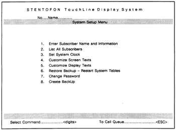
- ● Press "ESC" to reveal the "System Setup Menu".
<br\> <br\>
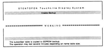
Step 1: Create Backup (command 8) This command initiates the backup system so that the names and information you are going to enter in Step 3, are automatically stored onto EEPROM. The command also restores the exchange programming you have already done (line A000 to A300 in the E62 table).
- ● Press digit 8.
The screen picture to the right is shown: The backup procedure will take several minutes.
Step 2: Set System Clock (command 3)
- ● Press digit 3 and enter the following information:
Write year    -  Press "Enter"
Write Month   -  Press "Enter"
Write Day     -  Press "Enter"
Write Hour    -  Press "Enter"
Write Minute  -  Press "Enter"
<br\>
- ● Return to the System Setup Menu by pressing "ESC"
<br\>
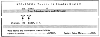
Step 3: Enter Subscriber Name and information (command 1) All existing subscriber numbers and names must be entered with this command. Also add function numbers with appropriate names (maximum 12 characters) to the system.
- ● Press digit 1 and enter the following information:
Write Number  -  Press "Enter"
Write Name    -  Press "Enter"
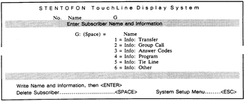
<br\> When the subscriber number/name or function number/name is written and you have pressed "Enter", the menu on the right appears.
- ● If you have entered a function number/name use this menu and follow the instructions in a).
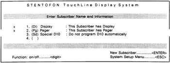
- ● If you have entered a subscriber number/name, press "Enter" once more, use the new menu which appears, and follow the instructions described in b).
- a) If you have entered a function number/name
- ● Press the corresponding sorting code (for Group Call; digit 2), then press "Enter"
(The procedure for entering the first function name/number is now completed, and the menu for subscriber numbers/nams appears (b). To enter new information, press "Enter" once more and the first menu will appear). <br\> The functions you enter should be given suitable names, including maximum 12 characters. To make it possible for the system to organize the menus in the "Info Feature" (refer to section 4.7), each function must also be given a sorting code (digit 1 to 6). Refer to beloq example. The following functions should be entered (standard numbers are shown):
No's. ..Function Name (example) .............. Function ......................... digit
9 ........ Own secretary ........................ (direct access to own secretary) . digit 6
00/01 .... Ans Gr. or All Call/Answer Page ...... (answer code no. 1 and no. 2) .... digit 3
70 ....... Present .............................. (call forwarding reset) .......... digit 1
71 ....... Call Preset .......................... (call fowarding preset) .......... digit 1
72 ....... Follow Me ............................ (call forwarding - Follow Me) .... digit 1
73 ....... Reset FolMe .......................... (Follow Me remote reset) ......... digit 1
79 ....... Program Step ......................... (Audio program Step) ............. digit 4
76 ....... Program On ........................... (Program ON) ..................... digit 4
80 ....... Program Off .......................... (Program OFF) .................... digit 4
81-83 .... Program 1-3 .......................... (Program 1-3) .................... digit 4
84 to 89 . All Call or Group Call no. 1 to 5 .... (All Call/Group Call no. 1 to 5) . digit 2
(The menu for function names/numbers appears only if you have a standard display system with the default name lengths).
<br\> TIP: You may wish to add a #secret" subscriber name/number to the system, so that the name and nnumber of a subscriber is not included in the Name List (directory), but shown only on the terminal and on your display station during connection with this subscriber. To hide this subscriber number/name, you have to enter a sorting code (digit) for this subscriber that is not listed in the above table (for example 0 or *. <br\>
- b) If you have entered an ordinary subscriber number/name (not a function), the following applies:
- ● To indivate that the subscriber has a display station (x), press digit 1 (similar to dialling 789 on a station). (To remove a station's display status, press digit 1 once more.
- ● To indicate that the subscriber has a Pager (x), press digit 2.
- ● If you want to save the existing programming for the Single Touch keys 8 and 9, press digit 3 (required e.g. for ITS stations). If not, the system will automatically assign the "Directory" and "Info" to these keys.
<br\>
- ● When all information is entered, return to System Setup Menu by pressing "ESC".
If you want to list all the names you have entered, you can execute command 2 "List All Subscribers". Refer to subsection 4.8.3. <br\>
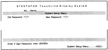
Step 4: Change Password (command 7) The very first time command 7 is executed, you can use "Enter" (as the "old" password does not exist"). The "new" password may then be entered. This password must be digits between 0 to 9 and letters A to F. The System Setup Menu is protected by this password to avoid unauthorized change of programming. (In addition, command 4 and 5 should be given special access restrictions, refer to Section 4.8.3).
- ● Press digit 7 and write old password, or press "Enter".
- ● Write new password (4 characters), then press "Enter".
- A wrong password entry will reveal an error message: "Wrong Password". If the wrong password is entered by mistake, press "ESC" and try again.
- When the password is entered, the system will automatically return to the System Setup Menu.
<br\>
Identifying the Display Stations
At this point, you have entered the Display Stations' intercom number/name and display indication (Di) via a terminal. If all the display stations were plugged in the wall sockets during installation (Section 3.5), the general display layout will automatically appear on the display (refer to Section 4.6). The date, time, number and name is shown (the following is an example):
1993-02-12 09:58
299 Bolten M.A.
- ► The station identification code 789 must be dialled whenever a station looses power due to unplugging.
If you have not plugged a display station in its wall socket, plug it in, and the following message appears on the display after a short moment:
Activate With
789
- ● Dial the station identification code 789.
The identification takes a couple of seconds.
  Own Number
299 PII54 Ri3800
After a short moment the display shows the following information:
1993-02-12 09:58
299 Bolten M.A.
General Display Layout
The Display Station has a display (LCD) with two lines of 16 characters each. The following example shows the display information when a station is in "stand-by" mode (normal idle). The display indicates the date, the time and the owner's staion number/name (may vary depending on language):
1993-02-12 09:58
299 Bolten M.A.
Numbers for the "Directory" and "Info" Feature
The Name List in the system makes it possible to have a "help" feature. This feature makes it easy for the intercom user to search for functions (after pressing the "Info" key), or to search for an intercom number for any subscriber in the system (after pressing the "Name" key).
In order to use the "Directory" and "Info" Feature, two Single Touch keys are assigned these features:
- Key 8 is assigned the "directory Feature"
- Key 9 is assigned the "Info Feature"
The keys are automatically assigned the "Directory" and "Info" Feature during station identification (unless you have "locked" the existing programming for these keys in the System Setup Menu "Enter Subscriber Name and Information").
Commands Used for Service And Customizing
routine Inspection / Correction of Tables
Every time a routine inspection/correction of tables is done, the followng operations must be done first:
- ● Dial E62, press READ, DCB0, then ACTIVATE.
If no communication is possible using E62:
- ● Press the green button until the lowet LED starts flashing. This will program the data line speed to 9600, and displable the software (both terminal and station displays are "dead" when the lowest LED flashes).
To restart normal operation of the board:
- ● Press the green button once more.
Note that the green button must be pressed before repeated cold start, if not malfuncion (reset) will occur.
Restore Backup - Restart System Tables
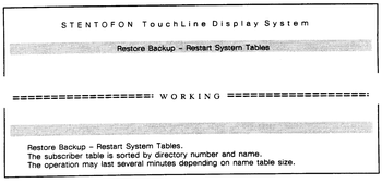
Restore Backup - Restart System Tables (command 6) is a service command that restores all name tables from EEPROM back-up. The command should be used only if problems occur, for example, if the alphabetical sorting does not work, or if it is impossible to upgrade the display status of a station.
- ● Press digit 6.
The screen on the right is shown.
When the procedure is completed, the DCB will make a reset, and the screen picture will automatically return to the "System Setup Menu".
List All Subscribers
Command 2 "List All Subscribers" is a service command which is useful during system setup or when new names or functions are entered.
- ● To list all subscribers, press digit 2, then "Enter"
- The subscriber names are listed alphabetically. Use the <ARROW> key to move to the next page.
- ● To search for a specific name, press ● and the first letter(s) in the name.
- The screen will show the name(s) of the person(s) you have searched for.
You can also perform a general search, using one or several criterias. You can search for names or functions by entering variuos search texts, for example, numbers, names, functions, subscribers with display indication (Di), subscribers with pager indication (Pg), etc.
- ● Use the <ARROW-right> key to position the cursor straight above the first character in the search criteria(s) you are to use.
- ● Enter the search text, then "Enter"
Example: You want to search for all the subscribers who have pagers:
- ● Position the cursor straight above P (in the text Pg) and write Pg, then press "Enter"
Example: You want to search for all the subscribers who have pagers and those with names starting with B:
- ● Position the cursor straight above the letter N (in Name) and write B.
- ● Position the cursor straight above the letter P (in the text Pg) and write Pg, then press "Enter".
Customizing Screen / Display Texts
Command 4 "Customize Display Text" and command 5 "Customize Screen Texts" should be given special access restrictions to avoid unauthorized changes. To execute these commands, value 0001 must be set to adress A208 in the operator's communication code E62 (refer to Appendix G). The default setting is 0000.
- ● If you are not planning to customize the screen/display texts, make sure that value 0000 is set to adress A208 in the E62 table.
Section 5.3, "Customizing Screen/Display Texts", provides detailed information on the necessary preparations and procedures.
Upgrading / Customizing
Introduction
The current version of the DCB board, version A6, is prepared for;
- ● EEPROM Back-up of Name Tables
- ● Customizing scrren texts
- ● Customizing display texts
To upgrade earlier versions of DCB boards (A5 or earlier), you need:
- ● EEPROM for back-up
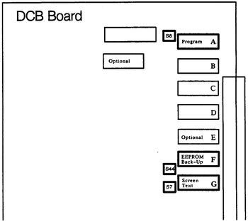
- Type 28256 - position F
- ● EPROM - DCB software version DCB 03.00
- Type 27512 - position A
- ● EPROM for Screen/Display Texts - DCB 03.00
- Type 27256 - position G
Upgrading to Software Version DCB 03.00
To upgrade your DCB board, perform the following procedure:
- CAUTION
- Before inserting or removing the DCBboard, make sure that the mains power is OFF. Be aware of static electricity.
- ● Remove the DCB board.
- ● Carefully remove "old" EPROMs, and insert new ones in the correct positions:
- - EPROM (DCB version 03.00) in position A
- - EPROM (DCB version 03.00) for screen/display texts in position G
- ● If you already have an EEPROM backup of the name tables (applies to software version DCB 02.00 only), do not remove this one (position F).
- ● If you do not have an EEPROM for back-up, insert the EEPROM in the correct position:
- - EEPROM for back-up in position F
- ● Make sure that the straps are correctly set;
    ●●●●
S8   | | (Strap position EPROM - position A)
    ●●●●
    ●●●●
S44 | |  (Strap position EEPROM - position F)
    ●●●●
    ●●●●
S7   | | (Strap position EPROM - position G)
    ●●●●
- ● Replace the DCB board.
- ● To enter programming mode, press the green button.
- ► The lowest LED on the DCB board flickers randomly, but is mostly off.
- ● From the programming panel:
- - Enter opcode E62, press READ, press DCB0, then ACT
- - Press CLEAR, A300, and then READ
- ● Follow the upgrade procedure in the table below.
- NOTE
- Do NOT execute command 01 (initialize NVRAM tables).
- If this is done, the contents of the EEPROM will be erased and all existing Name Tables will be destroyed.
If you already have an EEPROM backup of the name tables (applies to DCB 02.00 only), and just want to upgrade to software version DCB 03.00, you only need to execute command 02 and 03.
- NOTE
- Do not execute command 01 (initialize NVRAM tables) If this is done, the contents of the EEPROM will be erased and all Name Tables
- will be destroyed.
| Text: | Programming | Observe Display |
|---|---|---|
| Initialize Screen Texts *1 | ► Press 0201 | A:A300 B:0201 C:All off |
| Activate programming | ► Press ACTIVATE | A:A300 B:0000 C:All off |
| Select Terminal type *2 | ► Press 0302 | A:A300 B:0302 C:All off |
| Activate programming | ► Press ACTIVATE | A:A300 B:0000 C:All off |
| Create backup space in EEPROM *3 | ► Press 0600 | A:0600 B:dCb0 C:All off |
| Activate programming | ► Press ACTIVATE | A:A300 B:0000 C:All off |
| Leave programming mode | ► Press CANCEL | A:A300 B:0000 C:All off |
*1 The EPROM contains screen texts in your language.
*2 Terminal Type:
0301 = VT220 8-bit
0302 = VT220 7-bit
0303 = VT100
0304 = TDV2215
0305 = TDV2220
0306 = ADM11
*3 The command prepares the EEPROM for back-up. Use 00 for current length (16)
Error code Fxxx means more than 1000 names. Number of names possible using this name length.
- ● When the programming is completed, press the green button on the DCB board.
- ► The lowest LED on the DCB board flickers randomly, but is mostly off.
- ● To create an EEPROM back-up, execute command 8 in the System Setup Menu (for further information on "Create EEPROM back-up", refer to Section 4).
Customizing Screen / Display Texts
Preparing the DCB board
To modify screen/display texts according to customer needs, you have to prepare the DCB board. Perform the following procedure:
- CAUTION
- Before inserting or removing the DCB board, make sure that the mains power is OFF. Be aware of static electricity.
- ● Remove the DCB board.
- ● Remove the EEPROM used for back-up (in position F).
- Make sure to mark the EEPROM "Back-up".
- When you have completed the procedure, the EEPROM for back-up has to be replaced in this position).
- ● Insert an unused 256kbit EEPROM for the screen/display texts in position F. (This EEPROM must be ordered specially).
    ●●●●
S44 | |  (Strap position for Custom Screen Text EEPROM)
    ●●●●
- ● Replace the DCB board.
- ● If the lower LED on the DCB board does not blink, press the GREEN button.
- ● From the programming panel:
- - Enter opcode E62, press READ, press DCB0, then press ACT
- - Press CLEAR, A300, then READ
- ● Follow the procedure described below.
- NOTE
- Do NOT execute command 01 (initialize NVRAM tables).
| Text: | Programming | Observe Display |
|---|---|---|
| Execute command 0501 | ► Press 0501 | A:A300 B:0501 C:All off |
| Copy the language to EEPROM *1 | ► Press ACTIVATE | A:A300 B:0000 C:All off |
| Leave programming mode | ► Press CANCEL | A:A300 B:0000 C:All off |
*1 Wait. This procedure takes several seconds.
- ● When the programming is completed, press the green button on the DCB board.
- ► The lowest LED on the DCB board flickers randomly, but is mostly off.
- ● Switch the mains power OFF.
- ● Remove the DCB board.
- move the screen/display text EEPROM from position F to position G
    ●●●●
S7  | |  (Strap position for Screen/Display Text EEPROM)
    ●●●●
- ● Replace the backup EEPROM, which you have marked "back-up", into position F.
- ● Replace the DCB board.
- ● Switch the mains power ON.
- ● Press the red reset button on the DCB board.
At this point you have prepared the DCB board for customizing screen texts.
How to Customize Screen Texts / Display Texts
Command 4 "Customize Display Text" and command 5 "Customize Screen Texts" should be given special access restrictions to avoid unauthorized changes. To execute these commands, value 0001 must be set to adress A208 in the operator's communication code E62. The default value for this adress is 0000 (refer to appendix G).
- ● From the Programming Panel, set value 0001 to adress A208 in the E62 tabe.
- ● To customize screent texts or display texts, enter the System Setup Menu on your terminal and execute command 4 or commmand 5, respectively.
- ● Use the <ARROW-Up> key or <ARROW-Down> key to move to the next or previous text.
- Appendix J provides a default list of the default Screen Texts and Display Texts which are used in the Display System.
- ● When you have found the text you wish to change;
- - use the <ARROW-right> key to move to the first letter in the text and overwrite the existing text with the new one.
- - if necessary, use the <SPACE> key to delete a single letter.
- ● Press <ENTER>
- Applies to Screen texts only:
- If you want to see the changes you have done before you continue editing the next text, press <ESC> three times.
- ● When you have completed the procedure, press <ESC> to return to the System Setup Menu.
- ● To restrict access to command 5 and 5, set value 0000 to adress A208 in the E62 table.
Troubleshooting
This section provides a check list. It is intended to be a guide for the technician during commissioning of the STENTOFON TouchLine Display System.
- ● If problems occur, go through this check list.
CHECK LIST
|
|---|

