IP Video Doorstation Connections
From Zenitel Wiki
This article refers to the installation part of all STENTOFON IP Video Doorstations.
Contents
Introduction
The table below is an overview of the main connectors involved when installing the STENTOFON IP Video Doorstation.
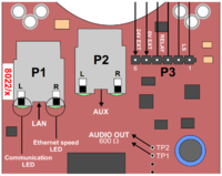
| LAN | 10/100 Mbps RJ-45 port for LAN (uplink) connection. Supports PoE (802.3af). Draws power from either spare line or signal line. |
| AUX | 10/100 Mbps RJ-45 port used by the IP camera |
| Input/Output | Pluggable screw terminal |
| Local Power | Plugable screw terminal, 19-27 VDC Idle 4W, max. 8W |
Power Supply
Audio Module
The IP Video Doorstation supports Power over Ethernet (PoE, IEEE 802.3 a-f) where power can be drawn from either the spare line or signal line.
If PoE is not available, the IP Video Doorstation can be connected to a 24 VDC local power supply.
See INCA Video Doorstation Board Connectors for local power supply connections.
Interface Module
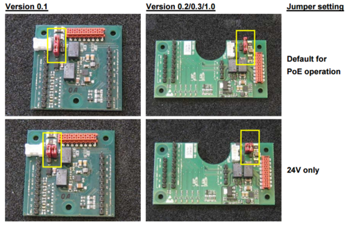
The jumpers J1 and J2 on the Interface Module are set to default for PoE operation on delivery. For hardware version 0.1, it is required to adjust the jumper setting to 24V only when using an external power supply. For hardware versions 0.2/0.3/1.0, it is not mandatory but recommended.
See INCA Video Doorstation Board Connectors for more details.
Network Connection
There are two RJ45 ports on the IP Video Doorstation:
- LAN port: for connecting to the network and the AlphaCom XE Audio Server.
- AUX port: for connecting to the IP Camera.
Input/Output Connections
There are I/O connection options for all IP Stations, except the IP Desktop Station and the IP Dual Display Station. These I/O connections include:
- 3 digital inputs (P4)
- Input 1 = call button
- 1 logical output (TP9)
- Controls CP-Cam viewer Pop-up
- 1 relay output (P3)
These connections are used as relay contacts for door lock control and external I/O devices.
For pin settings on the P3 and P4 connectors on the station board, see INCA Video Doorstation Board Connectors.
External add-on buttons
Up to six external buttons can be connected on the Interface Module. All six buttons (No. 2 to 7) can be utilized when operating with a AlphaCom IP system.
- Buttons 2 and 3 are connected to terminal X2 for version 0.1 and terminal X3 for versions 0.2/0.3/1.0, pins Z1 and Z2 as well as common ground.
- Buttons 4 to 7 are connected to terminal X3 for version 0.1 and terminal X4 for versions 0.2/0.3/1.0, pins Z1 to Z4 as well as common ground.
- Double and quadruple button modules as well as an emergency button can be delivered on request.
In case no 24V mains power supply is used, additional measures to avoid emission noise on the power cable must be taken!
In order to avoid damage, connect accessories only in a voltagefree state


