Difference between revisions of "Turbine Stations - Image recovery"
From Zenitel Wiki
(→Optional requirements) |
(→Phase one - Program the bootloader prepared for auto IP/tftp upgrade) |
||
| (29 intermediate revisions by the same user not shown) | |||
| Line 1: | Line 1: | ||
| − | This article describes how to flash a new image on a Zenitel Turbine device ("Compact" and "Extended" versions based on iMX28 processor). | + | This article describes how to flash a new image on a Zenitel Turbine device ("Compact" and "Extended" versions, based on iMX28 processor). |
| − | = Requirements = | + | == Requirements == |
* Download and install [[Downloads#Turbine_Test_and_Demo_Application|VS-Tools.msi]]. The PC application '''VS-ProductUpgrade''' is a part of this package. This software runs both a TFTP server, and USB boot of target. | * Download and install [[Downloads#Turbine_Test_and_Demo_Application|VS-Tools.msi]]. The PC application '''VS-ProductUpgrade''' is a part of this package. This software runs both a TFTP server, and USB boot of target. | ||
* A DHCP server handing out TFTP address to Turbine board using DHCP Option 66 (TFTP server address) | * A DHCP server handing out TFTP address to Turbine board using DHCP Option 66 (TFTP server address) | ||
| Line 11: | Line 11: | ||
| − | == | + | == Setup and connections == |
| − | + | [[File:TurbineRecovery1.PNG|thumb|left|500px|Principle connection. The upper cable ("USB to serial, TTL level") is optional]] | |
| − | |||
| − | |||
| − | |||
| − | |||
| − | |||
| − | |||
| − | |||
| − | |||
| − | |||
| − | |||
| − | |||
| − | |||
| − | |||
| − | [[File: | ||
| − | |||
| − | |||
| − | |||
<br style="clear:both;" /> | <br style="clear:both;" /> | ||
| + | === Optional connection=== | ||
| + | The process can optionally be monitored via the serial port of the board. This is not required, but could be useful for troubleshooting if issues appear during the process. You would need: | ||
| + | * A terminal emulator program. PuTTY is recommended | ||
| + | * A USB to Serial cable for serial connection from the PC to the circuit board | ||
| + | * See [[#Preparation of the optional USB to Serial converter cable|Preparation of the optional USB to Serial converter cable]] if you want to use this option | ||
| − | + | == Prepare the "VS-ProductUpgrade" application == | |
| − | |||
| − | |||
| − | |||
| − | |||
| − | |||
| − | |||
| − | |||
| − | |||
| − | |||
| − | = Prepare the VS-ProductUpgrade application = | ||
*Make sure no other TFTP server is running on the PC. | *Make sure no other TFTP server is running on the PC. | ||
*Launch '''VS-ProductUpgrade''' application from Windows start menu ('''Start''' > '''Vingtor-Stentofon''' > '''VS-ProductUpgrade'''). | *Launch '''VS-ProductUpgrade''' application from Windows start menu ('''Start''' > '''Vingtor-Stentofon''' > '''VS-ProductUpgrade'''). | ||
| Line 69: | Line 47: | ||
| − | == Example using "DHCP Server for Windows" == | + | === Example using "DHCP Server for Windows" === |
This is a simple and easy to use server that works good for this setup. | This is a simple and easy to use server that works good for this setup. | ||
Note! make sure you are not connected to other networks while doing this. | Note! make sure you are not connected to other networks while doing this. | ||
| − | Download and install from: http://www.dhcpserver.de/cms/ | + | * Download and install from: http://www.dhcpserver.de/cms/ |
| + | * Configure your computer with static ip 10.0.1.10. | ||
| + | * Configure the DHCP config file | ||
| − | + | Example of config file '''dhcpsrv.ini''' | |
| − | |||
| − | Example of config file dhcpsrv.ini | ||
[SETTINGS] | [SETTINGS] | ||
| Line 110: | Line 88: | ||
* ''Configure the ROOT path as required}} | * ''Configure the ROOT path as required}} | ||
| − | = Prepare USB boot from PC = | + | * Start the DHCP Server by running the '''dhcpsrv.exe''' |
| + | |||
| + | [[File:DHCP Inst Start.PNG|thumb|left|400px|Install, then Start the DHCP Server]] | ||
| + | <br style="clear:both;" /> | ||
| + | |||
| + | == Prepare USB boot from PC == | ||
Use the USB Mini B plug cable. | Use the USB Mini B plug cable. | ||
| Line 118: | Line 101: | ||
*The PC should indicate new USB Device | *The PC should indicate new USB Device | ||
| − | [[File:USB Device Discovered.PNG|thumb|left|500px|New USB device discovered]] | + | [[File:USB Device Discovered.PNG|thumb|left|500px|New USB device discovered by the PC]] |
<br style="clear:both;" /> | <br style="clear:both;" /> | ||
| + | |||
* '''Connect''' the Ethernet cable to the Turbine station. Now you have the following setup: (The usb-to-serial cable is optional) | * '''Connect''' the Ethernet cable to the Turbine station. Now you have the following setup: (The usb-to-serial cable is optional) | ||
| Line 125: | Line 109: | ||
<br style="clear:both;" /> | <br style="clear:both;" /> | ||
| − | = Run USB recovery programming of device(s) = | + | <br> |
| + | |||
| + | == Run USB recovery programming of device(s) == | ||
When all above is prepared all is set to start the full clean programming of the device(s). | When all above is prepared all is set to start the full clean programming of the device(s). | ||
| − | == Phase one - Program the bootloader prepared for auto IP/tftp upgrade == | + | === Phase one - Program the bootloader prepared for auto IP/tftp upgrade === |
*In the prepared VS-ProductUpgrade Tool press the big green button '''USB Boot Target''' | *In the prepared VS-ProductUpgrade Tool press the big green button '''USB Boot Target''' | ||
| − | * Watch the progress in the "TFTP Log/Output Console" window | + | * Watch the progress in the "TFTP Log/Output Console" window in the VS-ProductUpgrade Tool |
[[File:Image PhaseOne.PNG|thumb|left|300px|Output on "TFTP Log/Output Console"]] | [[File:Image PhaseOne.PNG|thumb|left|300px|Output on "TFTP Log/Output Console"]] | ||
| Line 135: | Line 121: | ||
*If serial cable is connected you can also observe the progress and see status in the terminal program | *If serial cable is connected you can also observe the progress and see status in the terminal program | ||
| − | *This programming will finish after just a couple of seconds. You might get a warning message | + | *This programming will finish after just a couple of seconds. You might get a warning message "Sent and OTP programmed MAC differs. STOP and investigate". This message can be ignored. |
*'''Remove''' USB and Ethernet cable. | *'''Remove''' USB and Ethernet cable. | ||
| − | == Phase two - Run full tftp image upgrade == | + | === Phase two - Run full tftp image upgrade === |
*Have the prepared VS-ProductUpgrade running | *Have the prepared VS-ProductUpgrade running | ||
*Connect the "phase one prepared" board to the PoE switch (do not connect the USB cable) | *Connect the "phase one prepared" board to the PoE switch (do not connect the USB cable) | ||
| Line 149: | Line 135: | ||
| − | The board will now reboot, and can | + | The board will now reboot, and start in normal operational mode. The board can be accessed through its web interface. |
| + | |||
| + | |||
| + | == Preparation of the optional USB to Serial converter cable == | ||
| + | |||
| + | The Turbine station has a TTL level serial interface to which we can connect during the upgrade process. For this purpose a USB to Serial converter cable can be used. Recommended cable is [http://uk.farnell.com/ftdi/ttl-232r-3v3/cable-usb-to-ttl-level-serial-conv/dp/1329311?Ntt=FTDI+-+TTL-232R-3V3+-+CABLE TTL-232R-3V3], available from Farnell. | ||
| + | |||
| + | This cable needs to be slightly modified as per photo below: | ||
| + | |||
| + | * Pin 1 = Black (GND) | ||
| + | * Pin 2 = Orange (Turbine RX) | ||
| + | * Pin 3 = Yellow (Turbine TX) | ||
| + | |||
| + | [[File:USB Serial orig.PNG|thumb|left|300px|Original cable]] | ||
| + | |||
| + | |||
| + | [[File:USB Serial mod.PNG|thumb|left|300px|Modified cable]] | ||
| + | <br style="clear:both;" /> | ||
| + | |||
| + | |||
| + | Insert the USB connector in the PC. The unit will now install itself. Make a note of which COM port number it is assigned to. You will also find it in the Device Manager. Baud rate: 115200. | ||
| + | |||
| + | [[File:USBSerialPort.PNG|thumb|left|500px|USB Serial Port in the Device Manager]] | ||
| + | <br style="clear:both;" /> | ||
[[Category: Turbine - Restore Factory Defaults and Software Upgrade]] | [[Category: Turbine - Restore Factory Defaults and Software Upgrade]] | ||
Latest revision as of 08:58, 21 June 2024
This article describes how to flash a new image on a Zenitel Turbine device ("Compact" and "Extended" versions, based on iMX28 processor).
Contents
Requirements
- Download and install VS-Tools.msi. The PC application VS-ProductUpgrade is a part of this package. This software runs both a TFTP server, and USB boot of target.
- A DHCP server handing out TFTP address to Turbine board using DHCP Option 66 (TFTP server address)
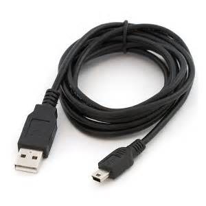
- A USB Mini B plug cable.
- Access to the physical circuit board.
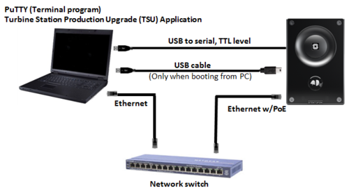
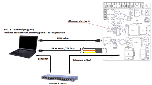
Setup and connections
Optional connection
The process can optionally be monitored via the serial port of the board. This is not required, but could be useful for troubleshooting if issues appear during the process. You would need:
- A terminal emulator program. PuTTY is recommended
- A USB to Serial cable for serial connection from the PC to the circuit board
- See Preparation of the optional USB to Serial converter cable if you want to use this option
Prepare the "VS-ProductUpgrade" application
- Make sure no other TFTP server is running on the PC.
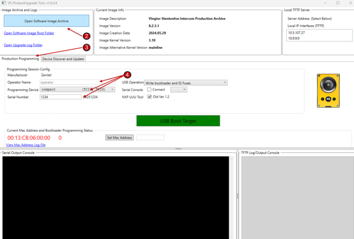
- Launch VS-ProductUpgrade application from Windows start menu (Start > Vingtor-Stentofon > VS-ProductUpgrade).
- Download the software image for Zenitel Devices based on iMX28. Image: vsft-prod-8.2.3.1.zip
- Load the software image using the Open Software Image Archive button.
- Activate tab Production Programming
- Insert input fields Operator Name, Programming Device and Serial Number.
Your application should look something like below programming a TCIS-1 Station:
Prepare the DHCP server
You can use any DHCP server, but you need to be able to configure DHCP option 66/Nextserver (TFTP server address) to point to the IP of the PC running VS-ProductUpgrade.
Example using "DHCP Server for Windows"
This is a simple and easy to use server that works good for this setup. Note! make sure you are not connected to other networks while doing this.
- Download and install from: http://www.dhcpserver.de/cms/
- Configure your computer with static ip 10.0.1.10.
- Configure the DHCP config file
Example of config file dhcpsrv.ini
[SETTINGS]
IPPOOL_1=10.0.1.100-120
IPBIND_1=10.0.1.10
AssociateBindsToPools=1
Trace=1
DeleteOnRelease=0
ExpiredLeaseTimeout=3600

[GENERAL]
LEASETIME=86400
NODETYPE=8
SUBNETMASK=255.255.255.0
NEXTSERVER=10.0.1.10
ROUTER_0=10.0.1.1

[DNS-SETTINGS]
EnableDNS=0

[TFTP-SETTINGS]
EnableTFTP=0
ROOT=C:\Programs\dhcpsrv2.5.2\wwwroot
WritePermission=1

[HTTP-SETTINGS]
EnableHTTP=0
ROOT=C:\Programs\dhcpsrv2.5.2\wwwroot

|
|
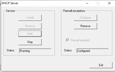
- Start the DHCP Server by running the dhcpsrv.exe
Prepare USB boot from PC
Use the USB Mini B plug cable.
- Disconnect the Ethernet cable from the station (you might leave USB to Serial converter cable connected, so you can view progress on PuTTY)
- Connect one end of the USB cable to the PC
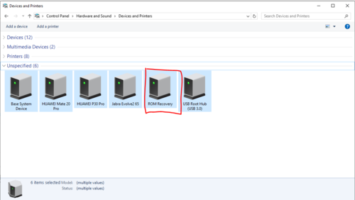
- Push and hold the "Recovery button" on the station (switch S200), and keep it pressed for 5 sec while connecting the USB cable to the station (connector J2 on "Compact, J3 on "Extended")
- The PC should indicate new USB Device
- Connect the Ethernet cable to the Turbine station. Now you have the following setup: (The usb-to-serial cable is optional)
Run USB recovery programming of device(s)
When all above is prepared all is set to start the full clean programming of the device(s).
Phase one - Program the bootloader prepared for auto IP/tftp upgrade
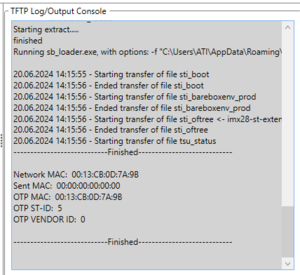
- In the prepared VS-ProductUpgrade Tool press the big green button USB Boot Target
- Watch the progress in the "TFTP Log/Output Console" window in the VS-ProductUpgrade Tool
- If serial cable is connected you can also observe the progress and see status in the terminal program
- This programming will finish after just a couple of seconds. You might get a warning message "Sent and OTP programmed MAC differs. STOP and investigate". This message can be ignored.
- Remove USB and Ethernet cable.
Phase two - Run full tftp image upgrade
- Have the prepared VS-ProductUpgrade running
- Connect the "phase one prepared" board to the PoE switch (do not connect the USB cable)
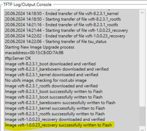
- The upgrade should now start automatically. Observe the progress in the "TFTP Log/Output Console" window. This process takes a while (typically approx. 4 minutes), so be patient.
- The process is finished when recovery successfully written to flash is displayed.
The board will now reboot, and start in normal operational mode. The board can be accessed through its web interface.
Preparation of the optional USB to Serial converter cable
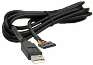
The Turbine station has a TTL level serial interface to which we can connect during the upgrade process. For this purpose a USB to Serial converter cable can be used. Recommended cable is TTL-232R-3V3, available from Farnell.
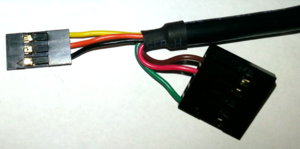
This cable needs to be slightly modified as per photo below:
- Pin 1 = Black (GND)
- Pin 2 = Orange (Turbine RX)
- Pin 3 = Yellow (Turbine TX)
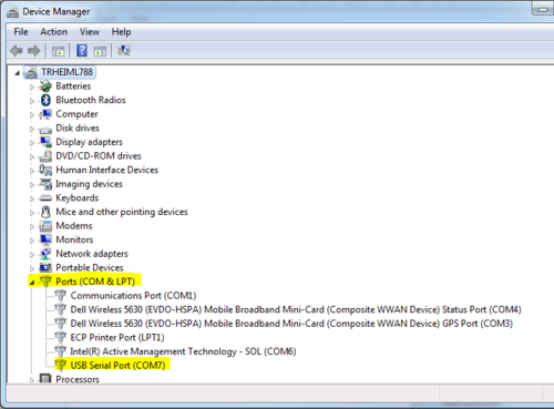
Insert the USB connector in the PC. The unit will now install itself. Make a note of which COM port number it is assigned to. You will also find it in the Device Manager. Baud rate: 115200.

