AsaCom - AlphaCom interface: Difference between revisions
From Zenitel Wiki
No edit summary |
|||
| (80 intermediate revisions by 2 users not shown) | |||
| Line 1: | Line 1: | ||
{{A}} | |||
[[File:AsaCom 1.PNG|thumb|right|600px|Interfacing AsaCom ASA101 and STENTOFON AlphaCom XE]] | [[File:AsaCom 1.PNG|thumb|right|600px|Interfacing AsaCom ASA101 and STENTOFON AlphaCom XE]] | ||
==SYSTEM BUILD-UP AND DESCRIPTION== | ==SYSTEM BUILD-UP AND DESCRIPTION== | ||
[[File:AsaCom 2.PNG|thumb| | [[File:AsaCom 2.PNG|thumb|350px|]] | ||
===General Description=== | ===General Description=== | ||
The existing ASACOM system ASA101 can be expanded by adding one or more STENTOFON AlphaCom | The existing ASACOM system ASA101 can be expanded by adding one or more STENTOFON AlphaCom Audio Servers. The two systems are interconnected via a SGA65008 interface unit that acts as a virtual AlphaCom Audio Server. The interface is handling all the signaling between the systems. Audio links are connected to the standard multi purpose interface cards for the respective system. Stations and equipment in both systems will interact as part of the same system. The AlphaCom Audio Server IP services can be accessed from the ASA101 system. | ||
interconnected via a SGA65008 interface unit that acts as a virtual | |||
AlphaCom | |||
the systems. Audio links are connected to the standard multi purpose | |||
interface cards for the respective system. Stations and equipment in | |||
both systems will interact as part of the same system. The AlphaCom | |||
IP services can be accessed from the ASA101 system. | |||
====Data==== | ====Data==== | ||
Data are transmitted via Ethernet link between the AlphaCom | Data are transmitted via Ethernet link between the AlphaCom Audio Server and the interface. The interface will convert and send information to the ASA101 system via the proprietary serial protocol ASKNEW. | ||
interface. The interface will convert and send information to the ASA101 | |||
system via the proprietary serial protocol ASKNEW. | |||
====Audio==== | ====Audio==== | ||
The audio interconnection between ASA101 and AlphaCom | The audio interconnection between ASA101 and AlphaCom Audio Server is analogue. | ||
analogue. | * There are maximum 4 channels in twisted pair cables between the multi purpose board(s) ETCB in the ASA101 and the multi purpose board AGA in AlphaCom. | ||
multi purpose board(s) ETCB in the ASA101 and the multi purpose | |||
board AGA in AlphaCom | |||
====Audio switching control (Duplex/Simplex)==== | ====Audio switching control (Duplex/Simplex)==== | ||
The voice switching will take place individually in the different systems. | The voice switching will take place individually in the different systems. | ||
====Programming==== | ====Programming==== | ||
Individual programming will be carried out in each system: | Individual programming will be carried out in each system: | ||
* In ASA101 the programming for ETCB is performed from a programming station | |||
programming station | * AlphaPro and AlphaWeb are used for the AlphaCom Audio Server part | ||
* Interface programming with standard Windows® text editor. | |||
===Basic System Features=== | ===Basic System Features=== | ||
All internal features in both systems will remain as they are. | All internal features in both systems will remain as they are. | ||
The following features will be included in the interface between ASA101 | The following features will be included in the interface between ASA101 and AlphaCom: | ||
and AlphaCom | |||
* Station to station calling, two-way hands free and private | * Station to station calling, two-way hands free and private | ||
* Display information - Call number of calling station | * Display information - Call number of calling station | ||
* Call request (Emergency Call) and queuing from stations in ASA101 to master stations in AlphaCom | * Call request (Emergency Call) and queuing from stations in ASA101 to master stations in AlphaCom. | ||
* Global number plan or prefix dialing from ASA101 | * Global number plan or prefix dialing from ASA101 | ||
* Door opening | * Door opening | ||
* Microphone mute | * Microphone mute | ||
* Camp-On-Busy | * Camp-On-Busy | ||
* Setup of internal All-Call and Group-Call in ASA101 from AlphaCom . | * Setup of internal All-Call and Group-Call in ASA101 from AlphaCom. | ||
* 2,3 or 4 digits in ASA. 4 digits in AlphaCom | * 2,3 or 4 digits in ASA. 4 digits in AlphaCom. | ||
===Software Description=== | ===Software Description=== | ||
| Line 53: | Line 36: | ||
the ETCB revisions GE 03.1 and higher. | the ETCB revisions GE 03.1 and higher. | ||
The system can be run on EXCP software revisions ASA5 and higher. | The system can be run on EXCP software revisions ASA5 and higher. | ||
====AlphaCom | ====AlphaCom Audio Server==== | ||
AMC-IP software | Minimum software requirement: AMC-IP software release 10.60.3.14. | ||
====Interface SGA 65008==== | ====Interface SGA 65008==== | ||
The | The '''ASA-ACE Application software 2.17''' is running under Windows XP® Professional operating system. | ||
XP® Professional operating system. | |||
===Interface description=== | ===Interface description=== | ||
The interface SGA65008 is setup as a Virtuel AlphaCom node in an | The interface SGA65008 is setup as a Virtuel AlphaCom node in an AlphaNet configuration. The interface consists of a 19”, 1U height rack housing including a built-in standard PC equipped with Intel® Atom 200/300 processor. The interface is running application software '''ASAAC.exe''' under Windows-XP® Professional to control the signaling to/from ASACOM protocol '''ASKNEW''' and the '''Stentofon Simple Link Layer-PC''' protocol used by AlphaCom. All customer specific setup, such as node numbers for the different systems, number of used channels, numbers for call request and Group call numbers to ASA101 are located in a Configuration file used by the application. <br/> | ||
AlphaNet configuration. The interface consists of a 19”, 1U height rack | Built-in in the housing is also an additional Serial converter board that holds 4 converters from the ASA101 ETCB current loop serial ports to 4 internal USB serial ports to communicate with the application program. In addition it holds 2 internal USB serial channels used for conversion from RS485 to USB serial and one USB serial port for control of internal watchdog. The RS485 port(s) can be used for optional ASA applications such as Alarm Call. <br/< | ||
housing including a built-in standard PC equipped with Intel® Atom | Maximum capacity for signaling and speech channels between the two systems is four channels. The audio channels are directly connected with | ||
200/300 processor. The interface is running application software | a 4-wire cable for each speech channel from the Multi purpose board ETCB in the ASA101 exchange to the General purpose Audio interface AGA in the AlphaCom Audio Server. <br/> | ||
Together with the interface it is delivered a complete cable set for the connection from ASA101 ETCB boards and AlphaCom AGA board to the interface. The cable set is made for one ETCB board with 2 channels and have also twisted pair cables for 2 channels to the AlphaCom AGA board. Length of cable in all directions is 10 meters. <br/> | |||
to/from ASACOM protocol | Cable set for 4 channels on request. <br/< | ||
Layer- | The AlphaCom and the interface are interconnected via: | ||
such as node numbers for the different systems, number of used | * one Ethernet link | ||
channels, numbers for call request and Group call numbers to ASA101 | The ASACOM and the interface are interconnected via: | ||
are located in a Configuration file used by the application. | |||
Built-in in the housing is also an additional Serial converter board that | |||
holds 4 converters from the ASA101 ETCB current loop serial ports to 4 | |||
internal USB serial ports to communicate with the application program. | |||
In addition it holds 2 internal USB serial channels used for conversion | |||
from RS485 to USB serial and one USB serial port for control of internal | |||
watchdog. The RS485 port(s) can be used for optional ASA applications | |||
such as Alarm Call. | |||
Maximum capacity for signaling and speech channels between the two | |||
systems is four channels. The audio channels are | |||
a 4-wire cable for each speech channel from the Multi purpose board | |||
ETCB in the ASA101 exchange to the General purpose Audio interface | |||
AGA in the AlphaCom | |||
Together with the interface it is delivered a complete cable set for the | |||
connection from ASA101 ETCB boards and AlphaCom AGA board to | |||
the interface. The cable set is made for one ETCB board with 2 | |||
channels and have also twisted pair cables for 2 channels to the | |||
AlphaCom AGA board. Length of cable in all directions is 10 meters. | |||
Cable set for 4 channels on request. | |||
The AlphaCom | |||
* one Ethernet link The ASACOM and the interface are interconnected via: | |||
* one or up to four current loop serial communication ports | * one or up to four current loop serial communication ports | ||
* optional RS485 communication port (E-bus) for Alarm call The audio links are provided via direct wire connections between the ETCB and AGA analogue interface boards: | * optional RS485 communication port (E-bus) for Alarm call | ||
The audio links are provided via direct wire connections between the ETCB and AGA analogue interface boards: | |||
* one or up to four 4-wire, 0 dBm audio links. | * one or up to four 4-wire, 0 dBm audio links. | ||
===Interface Front side=== | ===Interface Front side=== | ||
The front side has a LED panel for indication of the standard PC | The front side has a LED panel for indication of the standard PC | ||
behavior and power ON/OFF switch. | behavior and power ON/OFF switch. | ||
[[File:AsaCom 3.PNG|thumb| | [[File:AsaCom 3.PNG|thumb|left|600px|Interface Front side]] | ||
<br style="clear:both;" /> | |||
===Interface Rear side=== | ===Interface Rear side=== | ||
| Line 114: | Line 69: | ||
to ETCB is also found. | to ETCB is also found. | ||
#Status LED’s Channel 1. | |||
# Status LED’s Channel 2. | |||
# Status LED’s Channel 3. | |||
# Status LED’s Channel 4. | |||
# Status LED’s Run mode, Watchdog. | |||
# Status LED’s E-Bus RS485 port. | |||
# Status LED’s Auxiliary RS485 port. | |||
HEADER: Ribbon cable connection from ETCB boards. | HEADER: Ribbon cable connection from ETCB boards. | ||
[[File:AsaCom 4.PNG|thumb|left|600px|]] | |||
[[File:AsaCom 5.PNG|thumb|right|600px|]] | |||
<br style="clear:both;" /> | |||
===Installation. Wiring and Connections=== | ===Installation. Wiring and Connections=== | ||
| Line 146: | Line 101: | ||
===Audio Links ETCB – AlphaCom | ===Audio Links ETCB – AlphaCom=== | ||
The audio links are | The audio links are directly connected in between the ETCB boards and the AlphaCom AGA board. Audio connections are found on connector J2 of the ETCB board. The AGA board provides 6 audio channels between the exchanges but only 4 channels can be used for maximum capacity. The AGA board can be placed in any position. Pos 20-23 are recommended in XE26 to avoid modifications of the backplane. Use the same filter board with cable and connection board as ASLT. | ||
the AlphaCom AGA board. Audio connections are found on connector | |||
J2 of the ETCB board. The AGA board provides 6 audio channels | |||
between the exchanges but only 4 channels can be used for maximum | |||
capacity. The AGA board can be placed in any position. Pos 20-23 are | |||
recommended in | |||
same filter board with cable and connection board as ASLT. | |||
===Ethernet connection SGA65008- AlphaCom=== | |||
The Ethernet RJ45 connection ‘GLAN1’ in the interface is connected to the Ethernet RJ45 connection ‘ETH0’ in AlphaCom. Either direct or via an Ethernet switch connected to AlphaCom. | |||
<u>The cabling</u> | |||
[[File:AsaCom 6.PNG|thumb|left|600px|]] | |||
<br style="clear:both;" /> | |||
===Audio level adjustment on AGA board=== | ===Audio level adjustment on AGA board=== | ||
| Line 174: | Line 116: | ||
The receive level is adjusted by potentiometers on the AGA board. | The receive level is adjusted by potentiometers on the AGA board. | ||
Potentiometers for line 1 to 4 are turned to the left for max gain. | Potentiometers for line 1 to 4 are turned to the left for max gain. | ||
[[File:AsaCom 7.PNG|thumb|left|300px|]] | |||
<br style="clear:both;" /> | |||
===Audio level adjustment ETCB board=== | ===Audio level adjustment ETCB board=== | ||
| Line 186: | Line 126: | ||
See also chapter 2.7.4 ETCB channel programming | See also chapter 2.7.4 ETCB channel programming | ||
[[File:AsaCom 8.PNG|thumb|center|600px|]] | |||
<br style="clear:both;" /> | |||
==Settings and programming== | ==Settings and programming== | ||
===Interface settings=== | ===Interface settings=== | ||
To operate, a configuration file “ASA_Setup.ini” must be found. If the | To operate, a configuration file “ASA_Setup.ini” must be found. If the configuration file is missing at first time start-up, the file will be generated automatically with default settings. The configuration file must | ||
configuration file is missing at first time start-up, the file will be | be edited on-site with customer data for the whole system. | ||
generated automatically with default settings. The configuration file must | |||
be edited on-site with customer data for the whole system | |||
The file contains settings for communication with the AlphaCom Audio Server in an AlphaNet, such as IP-address, node number, Call request number(s) and conversion table for ASA Group and All-Call numbers. The file is | |||
also holding the settings for use of internal serial ports in the interface for communication with the ASA101. Below is the default configuration file for four channels. | |||
===Configuration file ASA_Setup.ini=== | ===Configuration file ASA_Setup.ini=== | ||
'''[TCP_SOCKET]''' | '''[TCP_SOCKET]''' | ||
:'''Socket_ip = 169.254.1.5 ;''' This is the default IP address of the AlphaCom . | |||
:'''Socket_port = 8000 ;''' The AlphaCom port used for IP service. The port must also be activated in the AlphaCom firewall. | |||
'''[NODES]''' | '''[NODES]''' | ||
: '''AMC_node = 1 ;''' AlphaCom node number | |||
:'''ASA_node = 7 ;''' Virtual AlphaCom Node number for the interface. The node must be created in AlphaCom. | |||
'''[SERIAL_COM]''' | '''[SERIAL_COM]''' | ||
:'''Com_Channel_1 = 6 ;''' Internal USB port used for ETCB Channel 1 | |||
:'''Com_Channel_2 = 5 ;''' Internal USB port used for ETCB Channel 2 | |||
:'''Com_Channel_3 = 4 ;''' Internal USB port used for ETCB Channel 3 | |||
:'''Com_Channel_4 = 3 ;''' Internal USB port used for ETCB Channel 4 Set = 0 if ETCB channel not used. | |||
:'''Com_EBUS = 8;''' Internal USB port for ETCB RS485. Used for special ASA applications, i.e. ‘Alarm Call’. Set = '''0''' if not used. | |||
:'''Com_AUX = 0;''' Auxiliary USB port for RS485. Used for special applications. Set = '''0''' if not used. | |||
:'''Com_MCU = 9;''' Internal USB port used for Watchdog. If set = '''0''' the Watchdog is not enabled. | |||
'''[E_BUS]''' | '''[E_BUS]''' | ||
:'''E_BUS_node = 3 ;''' The ETCB node number used for ASA ‘Emergency Call’ to AlphaCom. This must also be set in ETCB ‘General Setup’ address 43 and 44 for the appropriated ETCB. | |||
'''E_BUS_node = 3 ;''' The ETCB node number used for ASA ‘Emergency Call’ to AlphaCom . This must also be set in ETCB ‘General Setup’ address 43 and 44 for the appropriated ETCB. | |||
'''[ASA_PARAMETER]''' | '''[ASA_PARAMETER]''' | ||
:'''AC_Digits = 4;''' Not to be changed. '''AC number plan has to be 4 digits across the systems.''' | |||
The table for conversion of Group Call numbers in ASA dialed from AlphaCom. The numbers specified are the call numbers programmed in AlphaCom that will be converted to the call number in ASA. Example: Group_call_0 = 9990; | |||
'''Group_call_0 | '''Group_call_0''' This is the All Call group 0 in ASA with ASA call no. 000 '''= 9990'''; This is the ‘Global Number for AlphaNet’ specified in AlphaCom to set up the All Call in ASA. | ||
:'''Group_call_0 = 9990;''' | |||
'''Group_call_1 = 9991;''' | :'''Group_call_1 = 9991;''' | ||
'''Group_call_2 = 9992;''' | :'''Group_call_2 = 9992;''' | ||
'''Group_call_3 = 9993;''' | :'''Group_call_3 = 9993;''' | ||
'''Group_call_4 = 9994;''' | :'''Group_call_4 = 9994;''' | ||
'''Group_call_5 = 9995;''' | :'''Group_call_5 = 9995;''' | ||
'''Group_call_6 = 9996;''' | :'''Group_call_6 = 9996;''' | ||
'''Group_call_7 = 9997;''' | :'''Group_call_7 = 9997;''' | ||
'''Group_call_8 = 9998;''' | :'''Group_call_8 = 9998;''' | ||
'''Group_call_9 = 9999;''' | :'''Group_call_9 = 9999;''' | ||
'''ASA_mode_callback = yes;''' | :'''ASA_mode_callback = yes;''' | ||
‘Call Back’ parameter handles the calling method from ASA to AlphaCom. If set to = '''no''' the ASA stations can call directly to an AlphaCom station. If set to = '''yes''' the ASA stations will be disconnected after dialing and be called back as ‘B’ extension. This will allow post dialing from AlphaCom to ASA. | |||
:'''ASA_Convert_3_to_4_digit =yes''' | |||
Convert 3 digits from ASA to 4 digits in ACM and reversed. | |||
Example: ASA extension number is “234”. In ACM this extension is defined as ”1234”. When dialing from ASA the number “234” is converted to “1234” by the interface. When dialing ASA extension “1234” from ACM the number sent will be “234”, i.e. first digit removed. | |||
:'''ASA_first_digit = 1''' | |||
Left most digit added to the 3 digit ASA numbers. Only used if parameter '''ASA_Convert_3_to_4_digit''' is set = '''yes''' | |||
:'''[AC_PARAMETER]''' | |||
Trunk parameters are not used. Should always be set to = yes to allow signaling and voice communication between the systems. If set = '''no''' channels will be blocked. | |||
:'''Trunk_1 = yes;''' | |||
''' | :'''Trunk_2 = yes;''' | ||
''' | :'''Trunk_3 = yes;''' | ||
:'''Trunk_4 = yes;''' | |||
''' | The extension numbers in AlphaCom to be dialed from ASA to place the call in a ‘Call Request’ queue. This will allow post dialing from AlphaCom to ASA, i.e. control of door lock in ASA. | ||
:'''Call_request_number_1 = 1001;''' | |||
''' | :'''Call_request_number_2 = 1002;''' | ||
''' | :'''Call_request_number_3 = ;''' | ||
''' | :'''Call_request_number_4 = ;''' | ||
''' | :'''Call_request_number_5 = ;''' | ||
:'''Call_request_number_6 = ;''' | |||
:'''Call_request_number_7 = ;''' | |||
:'''Call_request_number_8 = ;''' | |||
'''Call_request_number_8 = ;''' | |||
:'''Call_request_number_9 = ;''' | |||
:'''Call_request_number_10 = ;''' | |||
===ASACOM Programming=== | ===ASACOM Programming=== | ||
| Line 328: | Line 251: | ||
channels, according to the table below. Used channels are channel 1 | channels, according to the table below. Used channels are channel 1 | ||
and 2. | and 2. | ||
[[File:AsaCom 9.PNG|thumb|left|600px|]] | |||
<br style="clear:both;" /> | |||
===ETCB General Setup=== | ===ETCB General Setup=== | ||
| Line 336: | Line 259: | ||
and 2 on each ETCB board. | and 2 on each ETCB board. | ||
[[File:AsaCom 10.PNG|thumb|left|600px|]] | |||
<br style="clear:both;" /> | |||
Call prefix for outgoing calls can be set in addresses 17 and 18. Default | Call prefix for outgoing calls can be set in addresses 17 and 18. Default | ||
prefix is 04 for both channels. | prefix is 04 for both channels. | ||
===ETCB Com port settings=== | ===ETCB Com port settings=== | ||
| Line 351: | Line 271: | ||
ports for communication with the interface are Com6 and Com7 on each | ports for communication with the interface are Com6 and Com7 on each | ||
board. | board. | ||
[[File:AsaCom 11.PNG|thumb|left|600px|]] | |||
<br style="clear:both;" /> | |||
===Optional Setup for Emergency Call=== | ===Optional Setup for Emergency Call=== | ||
| Line 358: | Line 278: | ||
made in free non-physical channels 5-14.This feature should be set in | made in free non-physical channels 5-14.This feature should be set in | ||
more than one channel to be able to handle several simultaneous calls. | more than one channel to be able to handle several simultaneous calls. | ||
[[File:AsaCom 12.PNG|thumb|left|600px|]] | |||
<br style="clear:both;" /> | |||
===ETCB Channel Programming=== | ===ETCB Channel Programming=== | ||
| Line 367: | Line 287: | ||
timeout etc. The channel has to be setup for the ‘ASKNEW’ protocol and | timeout etc. The channel has to be setup for the ‘ASKNEW’ protocol and | ||
set with the appropriate current loop port for the signaling. | set with the appropriate current loop port for the signaling. | ||
Note! Current loop port can not be the same for the channels on the | ''Note! Current loop port can not be the same for the channels on the same ETCB board.'' | ||
same ETCB board. | [[File:AsaCom 14.PNG|thumb|left|600px|]] | ||
<br style="clear:both;" /> | |||
[[File:AsaCom 15.PNG|thumb|left|600px|]] | |||
<br style="clear:both;" /> | |||
===Optional ETCB Channel programming for Alarm Call=== | ===Optional ETCB Channel programming for Alarm Call=== | ||
| Line 384: | Line 304: | ||
The setting above must be same for all non-physical channels used for | The setting above must be same for all non-physical channels used for | ||
Emergency Facility. | Emergency Facility. | ||
[[File:AsaCom 16.PNG|thumb|left|600px|]] | |||
<br style="clear:both;" /> | |||
===Additional ASACOM Programming=== | ===Additional ASACOM Programming=== | ||
| Line 401: | Line 321: | ||
===AlphaCom | ===AlphaCom programming=== | ||
This chapter is only giving an overview of the necessary programming for communication with the interface. For additional information about the AlphaCom features and programming refer to the ‘AlphaCom | |||
System Management and Operation manual’ and also the ‘AlphaPro manual’. | |||
===Configuration of nodes in AlphaPro=== | ===Configuration of nodes in AlphaPro=== | ||
* Define the new ASA101 Node for the Interface as Node Type ‘AlphaCom’. | |||
‘AlphaCom’. | * Add the ASA101 node to the network with ‘No AlphaNet Administration’ | ||
[[File:AsaCom 17.PNG|thumb|left|600px|]] | |||
<br style="clear:both;" /> | |||
In '''“AlphaPro/Exchange Information/Serial Ports”''' configure an ACDP | In '''“AlphaPro/Exchange Information/Serial Ports”''' configure an ACDP Link as TCP/IP-Server on port 8000 as '''Stentofon Simple Link Layer PC'''. The port has to equal the port setting in the interface .INI-file. | ||
Link as TCP/IP-Server on port 8000 as Stentofon Simple Link Layer | [[File:AsaCom 18.PNG|thumb|left|600px|]] | ||
<br style="clear:both;" /> | |||
Don’t forget to enable the port for the Firewall in AlphaWeb! | Don’t forget to enable the port for the Firewall in AlphaWeb! | ||
In '''“AlphaPro/Exchange Information/Net Routing”''' insert the new route for the ASACOM node. | |||
[[File:AsaCom 19.PNG|thumb|left|600px|]] | |||
<br style="clear:both;" /> | |||
In '''“AlphaPro/Exchange Information/Net Audio”''' creates, for each channel to be used, an ‘AlphaNet Audio Connection’. | |||
[[File:AsaCom 20.PNG|thumb|left|600px|]] | |||
<br style="clear:both;" /> | |||
===Programming of Global ASACOM Call numbers=== | ===Programming of Global ASACOM Call numbers=== | ||
The ASA101 call numbers or range of call numbers must be | The ASA101 call numbers or range of call numbers must be programmed as Global Numbers for AlphaNet in the AlphaCom node. This can be done by either programming every single extension number in ASA101 or in very large systems, 1 or 2 digits can be programmed as ASA101 Exchange prefix. | ||
programmed as Global Numbers for AlphaNet in the AlphaCom node. | ''Note: If exchange prefix dialing from AlphaCom is used, direct access keys (DAK) can not be used.'' | ||
This can be done by either programming every single extension number | ''Local Group and All Call in ASACOM for 10 groups can be accessed and setup from the AlphaCom exchange.'' | ||
in ASA101 or in very large systems, 1 or 2 digits can be programmed as | ''Also these numbers has to be programmed as ‘Global Numbers for AlphaNet’.'' | ||
ASA101 Exchange prefix. Note: If exchange prefix dialing from | |||
AlphaCom is used, direct access keys (DAK) can not be used. | |||
Local Group and All Call in ASACOM for 10 groups can be accessed | |||
and setup from the AlphaCom exchange. Also these numbers has to be | |||
programmed as ‘Global Numbers for AlphaNet’. | |||
===Single Global Numbers=== | ===Single Global Numbers=== | ||
| Line 452: | Line 361: | ||
feature 83. Add an appropriate display text and node number for the | feature 83. Add an appropriate display text and node number for the | ||
ASA system. | ASA system. | ||
[[File:AsaCom 21.PNG|thumb|left|600px|]] | |||
<br style="clear:both;" /> | |||
===Global Exchange Prefix=== | ===Global Exchange Prefix=== | ||
| Line 462: | Line 371: | ||
field. Add an appropriate display text and node number for the ASA | field. Add an appropriate display text and node number for the ASA | ||
system. | system. | ||
[[File:AsaCom 22.PNG|thumb|left|600px|]] | |||
<br style="clear:both;" /> | |||
===Group and All Call=== | ===Group and All Call=== | ||
| Line 474: | Line 382: | ||
internal numbers 000 to 009 in ASA101. Add an appropriate display text | internal numbers 000 to 009 in ASA101. Add an appropriate display text | ||
and node number for the ASA system. | and node number for the ASA system. | ||
[[File:AsaCom 23.PNG|thumb|left|600px|]] | |||
<br style="clear:both;" /> | |||
===Alarm Call from ASA=== | ===Alarm Call from ASA=== | ||
| Line 484: | Line 392: | ||
in the Directory number list. Numbers are 9790 to 9799 in window | in the Directory number list. Numbers are 9790 to 9799 in window | ||
below. Feature no.9. | below. Feature no.9. | ||
[[File:AsaCom 24.PNG|thumb|left|600px|]] | |||
<br style="clear:both;" /> | |||
Also specific call numbers for the ASA RS485 communication link to the | Also specific call numbers for the ASA RS485 communication link to the | ||
Interface node must be included. They are used to verify the | Interface node must be included. They are used to verify the | ||
functionality of the alarm communication links. Feature no. 9. | functionality of the alarm communication links. Feature no. 9. | ||
[[File:AsaCom 25.PNG|thumb|left|600px|]] | |||
<br style="clear:both;" /> | |||
Upon an Alarm Call from ASA the AlphaCom will receive the following | Upon an Alarm Call from ASA the AlphaCom will receive the following | ||
| Line 495: | Line 407: | ||
routing to certain CRM stations according to the received alarm number, | routing to certain CRM stations according to the received alarm number, | ||
can be specified in the AlphaPro Event handler. | can be specified in the AlphaPro Event handler. | ||
[[File:AsaCom 26.PNG|thumb|left|600px|]] | |||
<br style="clear:both;" /> | |||
[[File:AsaCom 27.PNG|thumb|left|600px|]] | |||
<br style="clear:both;" /> | |||
==Startup and Operation== | ==Startup and Operation== | ||
| Line 516: | Line 427: | ||
Default password: '''71629''' | Default password: '''71629''' | ||
[[File:AsaCom 28.PNG|thumb|left|600px|]] | |||
<br style="clear:both;" /> | |||
===Call handling=== | |||
The feature accessibility in the two systems will differ and follow the calling method and setting in the interface ASA_Setup.ini-file and the different systems. | |||
'''Important Notes:''' | '''Important Notes:''' | ||
<u>Post dialing from ASA101 and AlphaCom</u> | <u>'''Post dialing from ASA101 and AlphaCom'''</u> | ||
Post dialing from ASA is transmitted <u>only</u> if ASA is A-extension. Commands for door opening and manual voice control in ASA can <u>only</u> be received if ASA is B-extension. | |||
Other post dialing messages between ASA101 and AlphaCom are not transmitted! | |||
Therefore '''ASA mode call back''' is implemented in the interface setup .ini-file so that a calling ASA substation can receive door opening and manual voice controls (depending of the application). However, this | |||
method will be valid for all ASA extensions. | |||
===Interface setup for ‘No Call-Back’=== | ===Interface setup for ‘No Call-Back’=== | ||
| Line 548: | Line 453: | ||
AlphaCom. Post dialing <u>from ASA is not possible.</u> | AlphaCom. Post dialing <u>from ASA is not possible.</u> | ||
<u>'''Normal call from ASA:'''</u> | |||
From ASA dial the desired number, if number series programmed, or prefix + number in the AlphaCom and connection will be established. | |||
<u>'''Normal call from AlphaCom''':</u> | |||
From AlphaCom dial the desired single programmed number or the programmed exchange prefix + remaining digits in call number and the connection will be established. | |||
<u>''' | <u>'''Door station call from ASA to AlphaCom / Call Request:'''</u> | ||
Because of that the ASA door opening function can not be controlled directly from AlphaCom when ASA extension is initiating a call (A-side) in this calling method, the following programming can be made: | |||
Program the ASA door stations push button to dial the predefined AlphaCom ‘Call request’ number set in ASA_Setup.ini-file. Call will be disconnected and placed in queue at the AlphaCom station. When ‘Call | |||
Request’ is answered the AlphaCom extension has control over door lock function in ASA by pressing key 6. | |||
Program the ASA door stations push button to dial the predefined | |||
AlphaCom ‘Call request’ number set in ASA_Setup.ini-file. Call will be | |||
disconnected and placed in queue at the AlphaCom station. When ‘Call | |||
Request’ is answered the AlphaCom extension has control over door | |||
lock function in ASA by pressing key 6. | |||
Alarm | <u>'''ASA Alarm Call to AlphaCom:'''</u> | ||
Alarm Calls (if programmed in ASA and interface) dialed from ASA will be registered and sent on the RS485 serial link to the AlphaCom following the AlphaCom Event actions programmed. This call will not use any speech link. In the meanwhile, when placed in queue, the ASA station can be routed to an internal information channel for reception of a recorded spoken message. (Note, requires external equipment connected to an ASA ETCB channel setup for ACF.). | |||
When the AlphaCom station responds to the call, it will receive a busy tone as the ASA station is occupied. Communication will be established by using Priority function, press key 6 twice. | |||
===Use of ASA features. <u>Call from ASA</u>=== | ===Use of ASA features. <u>Call from ASA</u>=== | ||
| Line 605: | Line 493: | ||
'''Manual voice switch''' Press key A | '''Manual voice switch''' Press key A | ||
===Use of AlphaCom features. <u>Call from ASA</u>=== | ===Use of AlphaCom features. <u>Call from ASA</u>=== | ||
| Line 635: | Line 521: | ||
'''Manual voice switch*)''' Press key M | '''Manual voice switch*)''' Press key M | ||
* | * ''Requires setup or programming in ASA'' | ||
===Use of ASA features. <u>Call from AlphaCom</u>=== | ===Use of ASA features. <u>Call from AlphaCom</u>=== | ||
| Line 653: | Line 539: | ||
'''Transfer at No Answer''' Automatic after timeout | '''Transfer at No Answer''' Automatic after timeout | ||
* | * ''Requires setup or programming in ASA'' | ||
===Interface setup for ‘Call-Back’=== | ===Interface setup for ‘Call-Back’=== | ||
In this calling method the calls made from ASA will be valid for all ASA extensions. Regardless if prefix dialing or number series used, the dialing will be received by the interface and the call will be disconnected. The interface will then call back to the ASA extension and conversation is established. | |||
All post dialing from AlphaCom to ASA will be accessible, like door opening on direct call from ASA, manual remote voice switching across the interface etc. | |||
<u>'''Normal call and door station call:'''</u> | |||
From ASA dial the desired number, if number series programmed, or prefix + number in the AlphaCom. Call will be disconnected for a short moment and reconnected as B extension. | |||
If a Door Station Call answered, the AlphaCom extension has control over door lock function in ASA by pressing key 6. | |||
If a Door Station Call answered, the AlphaCom extension has control | |||
over door lock function in ASA by pressing key 6. | |||
<u>'''Call Request:'''</u> | |||
Program the ASA station push button to dial the predefined AlphaCom 'Call Request' number set in ASA_Setup.ini-file. Call will be disconnected and placed in queue at AlphaCom station. When Call Request is answered the AlphaCom extension has control over door lock function in ASA by pressing key 6. | |||
<u>'''ASA Alarm Call to AlphaCom:'''</u> | |||
Alarm Calls (if programmed in ASA and interface) dialed from ASA will be registered and sent on the RS485 serial link to the AlphaCom following the AlphaCom Event actions programmed. This call will not use any speech link. In the meanwhile, when placed in queue, the ASA station can be routed to an internal information channel for reception of a recorded spoken message. | |||
''Note! Requires external equipment connected to an ASA ETCB channel setup for ACF.'' | |||
When the AlphaCom station responds to the call, it will receive a busy tone as the ASA station is occupied. Communication will be established by using Priority function, press key 6 twice. | |||
When the AlphaCom station responds to the call, it will receive a busy | |||
tone as the ASA station is occupied. Communication will be established | |||
by using Priority function, press key 6 twice. | |||
===Use of ASA features. <u>Call from ASA</u>=== | ===Use of ASA features. <u>Call from ASA</u>=== | ||
| Line 709: | Line 573: | ||
'''Manual voice switch''' Press key A | '''Manual voice switch''' Press key A | ||
* ''Requires setup or programming in ASA'' | |||
===Use of AlphaCom features. <u>Call from ASA</u>=== | ===Use of AlphaCom features. <u>Call from ASA</u>=== | ||
| Line 720: | Line 584: | ||
'''Microphone mute''' Press key 0 | '''Microphone mute''' Press key 0 | ||
'''Inquiry / Brokers Call''' Dial 2 + AC or ASA extension. Press C to | '''Inquiry / Brokers Call''' Dial 2 + AC or ASA extension. Press C to return | ||
return | |||
'''Priority''' *) Press key 6 twice during received busy tone | |||
===Use of AlphaCom features. <u>Call from AlphaCom</u>=== | ===Use of AlphaCom features. <u>Call from AlphaCom</u>=== | ||
| Line 762: | Line 623: | ||
'''Transfer at No Answer *)''' Automatic after timeout | '''Transfer at No Answer *)''' Automatic after timeout | ||
* | * ''Requires setup or programming in ASA'' | ||
==Appendix== | ==Appendix== | ||
| Line 772: | Line 629: | ||
===Wiring Diagram for 4 channels=== | ===Wiring Diagram for 4 channels=== | ||
[[File:AsaCom 29.PNG|thumb|left|600px|]] | |||
<br style="clear:both;" /> | |||
===Pin out for ASA ETCB Connectors=== | ===Pin out for ASA ETCB Connectors=== | ||
[[File:AsaCom 30.PNG|thumb|left|600px|]] | |||
<br style="clear:both;" /> | |||
===Post dialing functions in short form=== | ===Post dialing functions in short form=== | ||
[[File:AsaCom 31.PNG|thumb|left|600px|]] | |||
<br style="clear:both;" /> | |||
| Line 800: | Line 660: | ||
===Technical Data SGA 65008=== | ===Technical Data SGA 65008=== | ||
{|border="1" | |||
|- | |||
'''Dimension (WxHxD):'''437 x 43 x 249mm, 19” / 1U | |'''Dimension (WxHxD):''' || 437 x 43 x 249mm, 19” / 1U | ||
|- | |||
'''Operating voltage:'''100-240 VAC | |'''Operating voltage:''' || 100-240 VAC | ||
|- | |||
'''Power consumption:'''200W | |'''Power consumption:''' || 200W | ||
|- | |||
'''Ethernet connection:'''1 x RJ45 10/100 Mbps | |'''Ethernet connection:'''|| 1 x RJ45 10/100 Mbps | ||
|- | |||
'''Max. distance to AlphaCom:'''100m according to IEEE 802.3 | |'''Max. distance to AlphaCom:''' || 100m according to IEEE 802.3 | ||
|- | |||
'''Max. distance to ASACOM:''' | |'''Max. distance to ASACOM:''' || 100m | ||
|- | |||
'''Audio:''' | |'''Audio:''' || 0 dB, 600 ohms, 300 – 3400 Hz | ||
|- | |||
'''Data protocols:''' | |'''Data protocols:''' || IP v4, TCP, UDP, HTTP,RTP, RTCP, DHCP, DiffServ, TOS, STENTOFON CCoIP®, ASKNEW | ||
IP v4, TCP, UDP, HTTP,RTP, RTCP, DHCP, DiffServ, TOS, STENTOFON CCoIP®, ASKNEW | |- | ||
|'''Operating temperature range:''' || 10°C to + 35°C | |||
'''Operating temperature range:''' | |- | ||
|'''Humidity:''' || 8% - 90% RH (non-condensing) | |||
'''Humidity:''' | |- | ||
|'''Weight:''' || 4.5 kg | |||
'''Weight:''' | |- | ||
|} | |||
[[Category:3rd party integration]] | [[Category:3rd party integration]] | ||
Latest revision as of 09:23, 11 January 2017

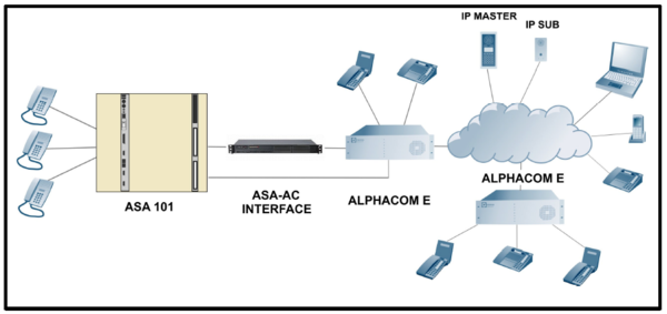
SYSTEM BUILD-UP AND DESCRIPTION
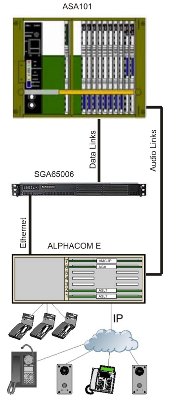
General Description
The existing ASACOM system ASA101 can be expanded by adding one or more STENTOFON AlphaCom Audio Servers. The two systems are interconnected via a SGA65008 interface unit that acts as a virtual AlphaCom Audio Server. The interface is handling all the signaling between the systems. Audio links are connected to the standard multi purpose interface cards for the respective system. Stations and equipment in both systems will interact as part of the same system. The AlphaCom Audio Server IP services can be accessed from the ASA101 system.
Data
Data are transmitted via Ethernet link between the AlphaCom Audio Server and the interface. The interface will convert and send information to the ASA101 system via the proprietary serial protocol ASKNEW.
Audio
The audio interconnection between ASA101 and AlphaCom Audio Server is analogue.
- There are maximum 4 channels in twisted pair cables between the multi purpose board(s) ETCB in the ASA101 and the multi purpose board AGA in AlphaCom.
Audio switching control (Duplex/Simplex)
The voice switching will take place individually in the different systems.
Programming
Individual programming will be carried out in each system:
- In ASA101 the programming for ETCB is performed from a programming station
- AlphaPro and AlphaWeb are used for the AlphaCom Audio Server part
- Interface programming with standard Windows® text editor.
Basic System Features
All internal features in both systems will remain as they are. The following features will be included in the interface between ASA101 and AlphaCom:
- Station to station calling, two-way hands free and private
- Display information - Call number of calling station
- Call request (Emergency Call) and queuing from stations in ASA101 to master stations in AlphaCom.
- Global number plan or prefix dialing from ASA101
- Door opening
- Microphone mute
- Camp-On-Busy
- Setup of internal All-Call and Group-Call in ASA101 from AlphaCom.
- 2,3 or 4 digits in ASA. 4 digits in AlphaCom.
Software Description
ASA 101
The Tie-Line Protocol communication software ASKNEW is included in the ETCB revisions GE 03.1 and higher. The system can be run on EXCP software revisions ASA5 and higher.
AlphaCom Audio Server
Minimum software requirement: AMC-IP software release 10.60.3.14.
Interface SGA 65008
The ASA-ACE Application software 2.17 is running under Windows XP® Professional operating system.
Interface description
The interface SGA65008 is setup as a Virtuel AlphaCom node in an AlphaNet configuration. The interface consists of a 19”, 1U height rack housing including a built-in standard PC equipped with Intel® Atom 200/300 processor. The interface is running application software ASAAC.exe under Windows-XP® Professional to control the signaling to/from ASACOM protocol ASKNEW and the Stentofon Simple Link Layer-PC protocol used by AlphaCom. All customer specific setup, such as node numbers for the different systems, number of used channels, numbers for call request and Group call numbers to ASA101 are located in a Configuration file used by the application.
Built-in in the housing is also an additional Serial converter board that holds 4 converters from the ASA101 ETCB current loop serial ports to 4 internal USB serial ports to communicate with the application program. In addition it holds 2 internal USB serial channels used for conversion from RS485 to USB serial and one USB serial port for control of internal watchdog. The RS485 port(s) can be used for optional ASA applications such as Alarm Call. <br/<
Maximum capacity for signaling and speech channels between the two systems is four channels. The audio channels are directly connected with
a 4-wire cable for each speech channel from the Multi purpose board ETCB in the ASA101 exchange to the General purpose Audio interface AGA in the AlphaCom Audio Server.
Together with the interface it is delivered a complete cable set for the connection from ASA101 ETCB boards and AlphaCom AGA board to the interface. The cable set is made for one ETCB board with 2 channels and have also twisted pair cables for 2 channels to the AlphaCom AGA board. Length of cable in all directions is 10 meters.
Cable set for 4 channels on request. <br/<
The AlphaCom and the interface are interconnected via:
- one Ethernet link
The ASACOM and the interface are interconnected via:
- one or up to four current loop serial communication ports
- optional RS485 communication port (E-bus) for Alarm call
The audio links are provided via direct wire connections between the ETCB and AGA analogue interface boards:
- one or up to four 4-wire, 0 dBm audio links.
Interface Front side
The front side has a LED panel for indication of the standard PC behavior and power ON/OFF switch.

Interface Rear side
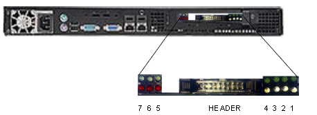
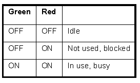
The rear side has the ordinary PC connections such as Ethernet, keyboard, mouse and terminal connections. The serial conversion board with connector for wiring and LED indications for the signaling channels to ETCB is also found.
- Status LED’s Channel 1.
- Status LED’s Channel 2.
- Status LED’s Channel 3.
- Status LED’s Channel 4.
- Status LED’s Run mode, Watchdog.
- Status LED’s E-Bus RS485 port.
- Status LED’s Auxiliary RS485 port.
HEADER: Ribbon cable connection from ETCB boards.
Installation. Wiring and Connections
Together with the interface it is delivered a complete cable set for the connection from ASA101 ETCB boards to the interface. The cable set is made for one ETCB board, two speech links cannels and twisted pair cables for speech channels to the AlphaCom AGA board. Length of cables in all directions is 10 meters.
Serial Data Links ETCB – SGA65008
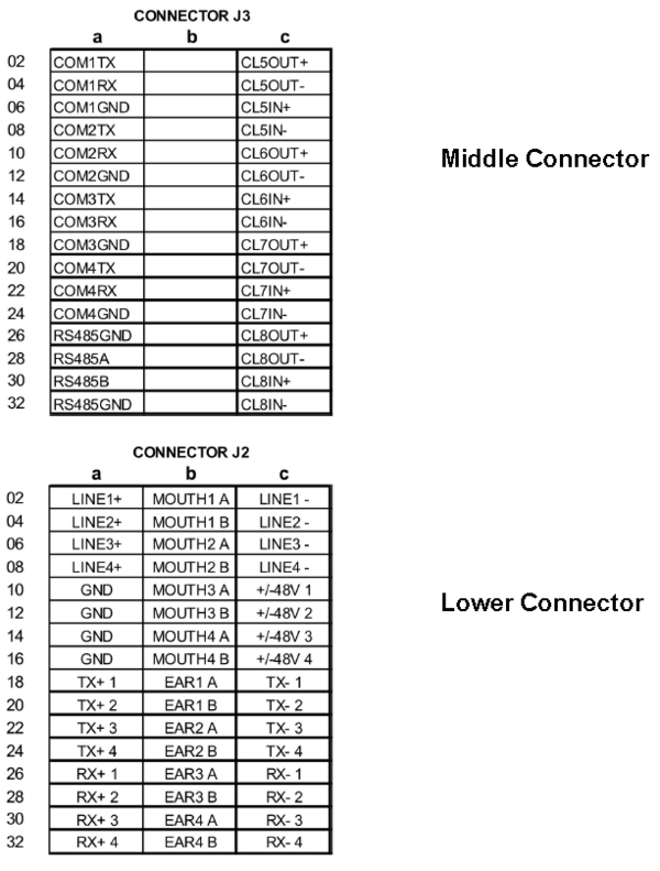
Each of the ETCB boards in ASA101 is using two current loop serial ports. These ports are located on board front connector J3. The used ports are port 6 and port 7 on each board which are connected to the ribbon cable header in the interface.
Audio Links ETCB – AlphaCom
The audio links are directly connected in between the ETCB boards and the AlphaCom AGA board. Audio connections are found on connector J2 of the ETCB board. The AGA board provides 6 audio channels between the exchanges but only 4 channels can be used for maximum capacity. The AGA board can be placed in any position. Pos 20-23 are recommended in XE26 to avoid modifications of the backplane. Use the same filter board with cable and connection board as ASLT.
Ethernet connection SGA65008- AlphaCom
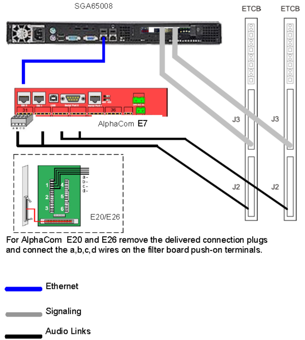
The Ethernet RJ45 connection ‘GLAN1’ in the interface is connected to the Ethernet RJ45 connection ‘ETH0’ in AlphaCom. Either direct or via an Ethernet switch connected to AlphaCom.
The cabling
Audio level adjustment on AGA board
The transmit level is fixed and cannot be adjusted in the AlphaCom. The receive level is adjusted by potentiometers on the AGA board. Potentiometers for line 1 to 4 are turned to the left for max gain.

Audio level adjustment ETCB board
The audio gain is set by programming for both transmit and receive in the ETCB channel setup. The settings are located in the addresses shown below and should be set for all used channels. Default is all channels set for 0 dB.
See also chapter 2.7.4 ETCB channel programming

Settings and programming
Interface settings
To operate, a configuration file “ASA_Setup.ini” must be found. If the configuration file is missing at first time start-up, the file will be generated automatically with default settings. The configuration file must be edited on-site with customer data for the whole system.
The file contains settings for communication with the AlphaCom Audio Server in an AlphaNet, such as IP-address, node number, Call request number(s) and conversion table for ASA Group and All-Call numbers. The file is also holding the settings for use of internal serial ports in the interface for communication with the ASA101. Below is the default configuration file for four channels.
Configuration file ASA_Setup.ini
[TCP_SOCKET]
- Socket_ip = 169.254.1.5 ; This is the default IP address of the AlphaCom .
- Socket_port = 8000 ; The AlphaCom port used for IP service. The port must also be activated in the AlphaCom firewall.
[NODES]
- AMC_node = 1 ; AlphaCom node number
- ASA_node = 7 ; Virtual AlphaCom Node number for the interface. The node must be created in AlphaCom.
[SERIAL_COM]
- Com_Channel_1 = 6 ; Internal USB port used for ETCB Channel 1
- Com_Channel_2 = 5 ; Internal USB port used for ETCB Channel 2
- Com_Channel_3 = 4 ; Internal USB port used for ETCB Channel 3
- Com_Channel_4 = 3 ; Internal USB port used for ETCB Channel 4 Set = 0 if ETCB channel not used.
- Com_EBUS = 8; Internal USB port for ETCB RS485. Used for special ASA applications, i.e. ‘Alarm Call’. Set = 0 if not used.
- Com_AUX = 0; Auxiliary USB port for RS485. Used for special applications. Set = 0 if not used.
- Com_MCU = 9; Internal USB port used for Watchdog. If set = 0 the Watchdog is not enabled.
[E_BUS]
- E_BUS_node = 3 ; The ETCB node number used for ASA ‘Emergency Call’ to AlphaCom. This must also be set in ETCB ‘General Setup’ address 43 and 44 for the appropriated ETCB.
[ASA_PARAMETER]
- AC_Digits = 4; Not to be changed. AC number plan has to be 4 digits across the systems.
The table for conversion of Group Call numbers in ASA dialed from AlphaCom. The numbers specified are the call numbers programmed in AlphaCom that will be converted to the call number in ASA. Example: Group_call_0 = 9990;
Group_call_0 This is the All Call group 0 in ASA with ASA call no. 000 = 9990; This is the ‘Global Number for AlphaNet’ specified in AlphaCom to set up the All Call in ASA.
- Group_call_0 = 9990;
- Group_call_1 = 9991;
- Group_call_2 = 9992;
- Group_call_3 = 9993;
- Group_call_4 = 9994;
- Group_call_5 = 9995;
- Group_call_6 = 9996;
- Group_call_7 = 9997;
- Group_call_8 = 9998;
- Group_call_9 = 9999;
- ASA_mode_callback = yes;
‘Call Back’ parameter handles the calling method from ASA to AlphaCom. If set to = no the ASA stations can call directly to an AlphaCom station. If set to = yes the ASA stations will be disconnected after dialing and be called back as ‘B’ extension. This will allow post dialing from AlphaCom to ASA.
- ASA_Convert_3_to_4_digit =yes
Convert 3 digits from ASA to 4 digits in ACM and reversed.
Example: ASA extension number is “234”. In ACM this extension is defined as ”1234”. When dialing from ASA the number “234” is converted to “1234” by the interface. When dialing ASA extension “1234” from ACM the number sent will be “234”, i.e. first digit removed.
- ASA_first_digit = 1
Left most digit added to the 3 digit ASA numbers. Only used if parameter ASA_Convert_3_to_4_digit is set = yes
- [AC_PARAMETER]
Trunk parameters are not used. Should always be set to = yes to allow signaling and voice communication between the systems. If set = no channels will be blocked.
- Trunk_1 = yes;
- Trunk_2 = yes;
- Trunk_3 = yes;
- Trunk_4 = yes;
The extension numbers in AlphaCom to be dialed from ASA to place the call in a ‘Call Request’ queue. This will allow post dialing from AlphaCom to ASA, i.e. control of door lock in ASA.
- Call_request_number_1 = 1001;
- Call_request_number_2 = 1002;
- Call_request_number_3 = ;
- Call_request_number_4 = ;
- Call_request_number_5 = ;
- Call_request_number_6 = ;
- Call_request_number_7 = ;
- Call_request_number_8 = ;
- Call_request_number_9 = ;
- Call_request_number_10 = ;
ASACOM Programming
The ETCB board(s) used has to be installed in the exchange according to the standard procedure found in the ‘ASA Installation Manual’ to get access to the internal programming of the boards. All programming of ETCB is taking place from a programming station. ECT Programming Tool can not be used. Full documentation of ETCB features and programming can be found in the ‘ETCB Manual’
ETCB Jumpers
The boards have to be set for 4-wire audio connections for the used channels, according to the table below. Used channels are channel 1 and 2.

ETCB General Setup
Used physical ETCB channels have to setup for ‘Tie Line’, function type 014. Setup is made in addresses 01-04. Used channels are channel 1 and 2 on each ETCB board.

Call prefix for outgoing calls can be set in addresses 17 and 18. Default
prefix is 04 for both channels.
ETCB Com port settings
Baud rate for com ports are located in addresses 39 to 42. Address 39, Com5 is dedicated for RS485 communication to special application programs and if used the port must be set to 9600b/s. Used current loop ports for communication with the interface are Com6 and Com7 on each board.

Optional Setup for Emergency Call
The Emergency Call feature doe’s not use any physical cannel. Setup is made in free non-physical channels 5-14.This feature should be set in more than one channel to be able to handle several simultaneous calls.

ETCB Channel Programming
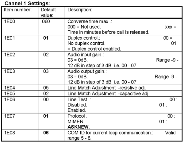
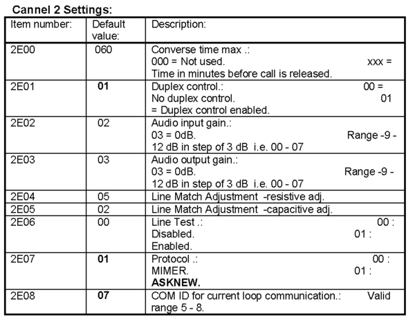
Each used channel has a number of settings that can be adjusted for the installation, such as audio levels for speech in/out, use of duplex control (CCDX voice switch function) at outgoing calls, conversation timeout etc. The channel has to be setup for the ‘ASKNEW’ protocol and set with the appropriate current loop port for the signaling.
Note! Current loop port can not be the same for the channels on the same ETCB board.
Optional ETCB Channel programming for Alarm Call
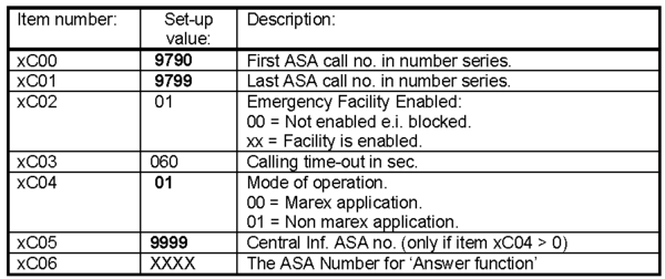
The call from ASA101 will be placed to an ETCB channel programmed for Central Information, to receive a spoken message during the transmission and placement in AlphaCom Call request queue. The call number for the physical Information channel must match the call number set in the ETCB address xC05. For additional programming of an Information channel, see the ETCB ‘ACF-tech’ manual.
The setting above must be same for all non-physical channels used for Emergency Facility.
Additional ASACOM Programming
The basic external call dialing from ASA101 upon installation of ETCB board(s) will be accessed with prefix dialing, default ‘04’, for all channels. In case of common numbering scheme for the two systems, single AlphaCom extension numbers or number series can be programmed. This follows the standard programming for the ASA101 ‘Tie Line’ feature and is performed by adding new line records with first and last call numbers in the number series. This has to be done for all used ETCB channels.
AlphaCom programming
This chapter is only giving an overview of the necessary programming for communication with the interface. For additional information about the AlphaCom features and programming refer to the ‘AlphaCom System Management and Operation manual’ and also the ‘AlphaPro manual’.
Configuration of nodes in AlphaPro
- Define the new ASA101 Node for the Interface as Node Type ‘AlphaCom’.
- Add the ASA101 node to the network with ‘No AlphaNet Administration’
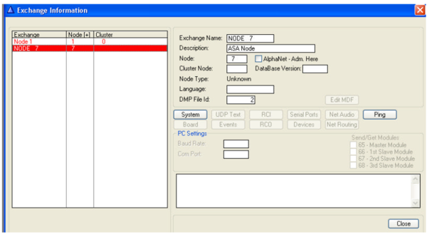
In “AlphaPro/Exchange Information/Serial Ports” configure an ACDP Link as TCP/IP-Server on port 8000 as Stentofon Simple Link Layer PC. The port has to equal the port setting in the interface .INI-file.
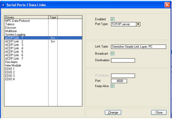
Don’t forget to enable the port for the Firewall in AlphaWeb!
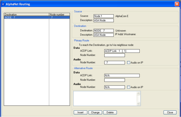
In “AlphaPro/Exchange Information/Net Routing” insert the new route for the ASACOM node.
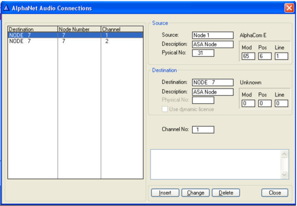
In “AlphaPro/Exchange Information/Net Audio” creates, for each channel to be used, an ‘AlphaNet Audio Connection’.
Programming of Global ASACOM Call numbers
The ASA101 call numbers or range of call numbers must be programmed as Global Numbers for AlphaNet in the AlphaCom node. This can be done by either programming every single extension number in ASA101 or in very large systems, 1 or 2 digits can be programmed as ASA101 Exchange prefix.
Note: If exchange prefix dialing from AlphaCom is used, direct access keys (DAK) can not be used.
Local Group and All Call in ASACOM for 10 groups can be accessed and setup from the AlphaCom exchange.
Also these numbers has to be programmed as ‘Global Numbers for AlphaNet’.
Single Global Numbers
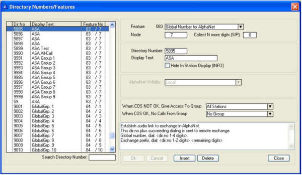
Insert the ASA101 call number as ‘Global Numbers for AlphaNet’, feature 83. Add an appropriate display text and node number for the ASA system.
Global Exchange Prefix
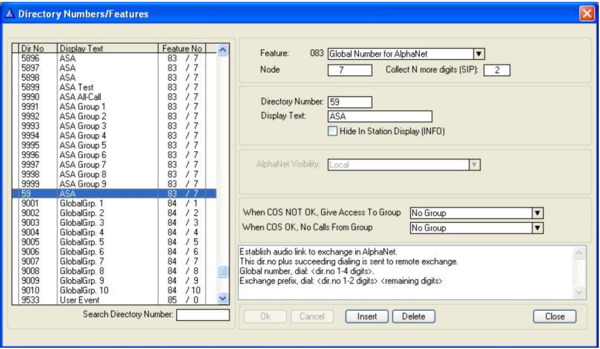
Insert the ASA101 exchange call prefix, one or two digits, as ‘Global Numbers for AlphaNet’, feature 83. Note that call numbers has to be 4 digits so add remaining digits to be dialed in the ‘Collect N more digits’ field. Add an appropriate display text and node number for the ASA system.
Group and All Call
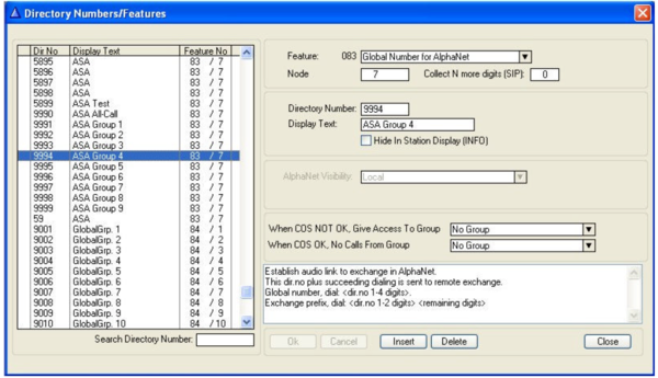
The Group and All Call numbers have also to be specified as ‘Global Numbers for AlphaNet’, with feature 83. The numbers must correspond to the numbers in the ‘ASA-setup.ini’ file for the interface. The numbers dialed from AlphaCom will be converted by the interface to the standard internal numbers 000 to 009 in ASA101. Add an appropriate display text and node number for the ASA system.
Alarm Call from ASA
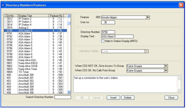
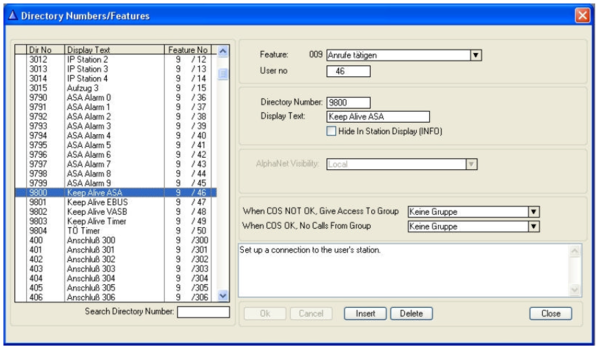
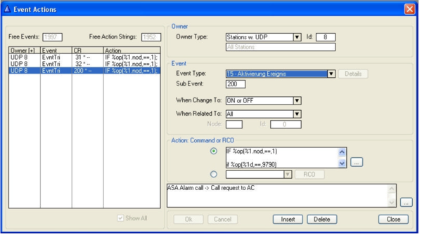
Alarm Calls generated from ASA can be routed to a station in AlphaCom. This is made by creating an ‘Event’ in the Event Action setup. In addition, the alarm numbers sent from ASA must be included in the Directory number list. Numbers are 9790 to 9799 in window below. Feature no.9.
Also specific call numbers for the ASA RS485 communication link to the Interface node must be included. They are used to verify the functionality of the alarm communication links. Feature no. 9.
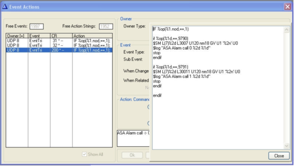
Upon an Alarm Call from ASA the AlphaCom will receive the following message string: $ER U15 U200 U1 U1 L9790 U3 Lxxxx where Lxxx is the ASA extension number. The actions to be taken, and routing to certain CRM stations according to the received alarm number, can be specified in the AlphaPro Event handler.
Startup and Operation
Interface Startup
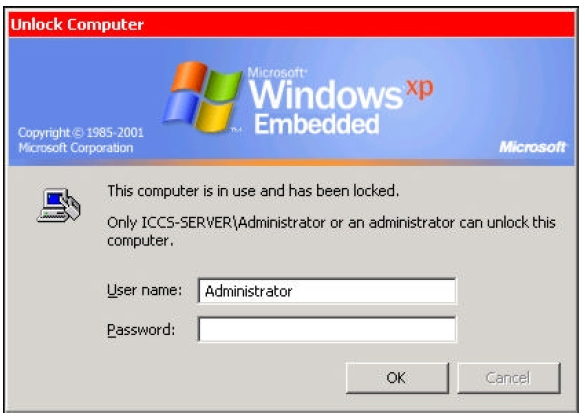
The interface application program will start automatically at power up. The built-in serial converter board has a watchdog function that will be activated in case of erroneous situations. This will cause a restart of the interface hardware and a restart of the application program. If the application software is terminated and restarted by administrator, the application is started, but a new login with username and password must be done before full access to the system and files is possible.
Default username: Administrator
Default password: 71629
Call handling
The feature accessibility in the two systems will differ and follow the calling method and setting in the interface ASA_Setup.ini-file and the different systems.
Important Notes:
Post dialing from ASA101 and AlphaCom
Post dialing from ASA is transmitted only if ASA is A-extension. Commands for door opening and manual voice control in ASA can only be received if ASA is B-extension.
Other post dialing messages between ASA101 and AlphaCom are not transmitted!
Therefore ASA mode call back is implemented in the interface setup .ini-file so that a calling ASA substation can receive door opening and manual voice controls (depending of the application). However, this method will be valid for all ASA extensions.
Interface setup for ‘No Call-Back’
This is the normal setting for ‘A’ to ‘B’ direct connection. If call is initiated from ASA, post dialing from ASA to AlphaCom is possible. Post dialing from AlphaCom to ASA is not possible.
If call is initiated from AlphaCom then post dialing is possible from AlphaCom. Post dialing from ASA is not possible.
Normal call from ASA:
From ASA dial the desired number, if number series programmed, or prefix + number in the AlphaCom and connection will be established.
Normal call from AlphaCom:
From AlphaCom dial the desired single programmed number or the programmed exchange prefix + remaining digits in call number and the connection will be established.
Door station call from ASA to AlphaCom / Call Request:
Because of that the ASA door opening function can not be controlled directly from AlphaCom when ASA extension is initiating a call (A-side) in this calling method, the following programming can be made:
Program the ASA door stations push button to dial the predefined AlphaCom ‘Call request’ number set in ASA_Setup.ini-file. Call will be disconnected and placed in queue at the AlphaCom station. When ‘Call Request’ is answered the AlphaCom extension has control over door lock function in ASA by pressing key 6.
ASA Alarm Call to AlphaCom:
Alarm Calls (if programmed in ASA and interface) dialed from ASA will be registered and sent on the RS485 serial link to the AlphaCom following the AlphaCom Event actions programmed. This call will not use any speech link. In the meanwhile, when placed in queue, the ASA station can be routed to an internal information channel for reception of a recorded spoken message. (Note, requires external equipment connected to an ASA ETCB channel setup for ACF.).
When the AlphaCom station responds to the call, it will receive a busy tone as the ASA station is occupied. Communication will be established by using Priority function, press key 6 twice.
Use of ASA features. Call from ASA
Abbreviated dialing *) Press function key F1-F3 or digit key 0-9+A
Camp-On Busy Automatic
‘Hurry-up’ signal Press A-key during received busy tone
Priority *) Press A-key twice during received busy tone
Microphone mute *) Press key 4
Door Opening Press key 6
Manual voice switch Press key A
Use of AlphaCom features. Call from ASA
Manual voice switch press key M
Door Opening Not possible
Microphone mute*) Press key 0
inquiry/brokers call Dial 2 + AC or ASA extension. Press C to return
Use of AlphaCom features. Call from AlphaCom
Abbreviated dialing Press desired DAK-key
Camp-On Busy automatic
Hurry-up’ signal Press M-key during received busy tone
Priority Press key 6 twice during received busy tone
Microphone mute Press key 0
Door Opening Press key 6
Manual voice switch*) Press key M
* Requires setup or programming in ASA
Use of ASA features. Call from AlphaCom
Manual voice switch Press key A
Door Opening Not possible
Microphone mute *) Press key 4
Inquiry / Return from Inquiry Dial 00 + AC or ASA extension. Press B to return
Secretary transfer *) Automatic
Transfer at No Answer Automatic after timeout
* Requires setup or programming in ASA
Interface setup for ‘Call-Back’
In this calling method the calls made from ASA will be valid for all ASA extensions. Regardless if prefix dialing or number series used, the dialing will be received by the interface and the call will be disconnected. The interface will then call back to the ASA extension and conversation is established.
All post dialing from AlphaCom to ASA will be accessible, like door opening on direct call from ASA, manual remote voice switching across the interface etc.
Normal call and door station call:
From ASA dial the desired number, if number series programmed, or prefix + number in the AlphaCom. Call will be disconnected for a short moment and reconnected as B extension.
If a Door Station Call answered, the AlphaCom extension has control over door lock function in ASA by pressing key 6.
Call Request: Program the ASA station push button to dial the predefined AlphaCom 'Call Request' number set in ASA_Setup.ini-file. Call will be disconnected and placed in queue at AlphaCom station. When Call Request is answered the AlphaCom extension has control over door lock function in ASA by pressing key 6.
ASA Alarm Call to AlphaCom:
Alarm Calls (if programmed in ASA and interface) dialed from ASA will be registered and sent on the RS485 serial link to the AlphaCom following the AlphaCom Event actions programmed. This call will not use any speech link. In the meanwhile, when placed in queue, the ASA station can be routed to an internal information channel for reception of a recorded spoken message.
Note! Requires external equipment connected to an ASA ETCB channel setup for ACF.
When the AlphaCom station responds to the call, it will receive a busy tone as the ASA station is occupied. Communication will be established by using Priority function, press key 6 twice.
Use of ASA features. Call from ASA
Abbreviated dialing *) Press function key F1-F3 or digit key 0-9+A
Camp-On Busy Automatic
Microphone mute *) Press key 4
Manual voice switch Press key A
* Requires setup or programming in ASA
Use of AlphaCom features. Call from ASA
Manual voice switch Press key M
Door Opening Press key 6
Microphone mute Press key 0
Inquiry / Brokers Call Dial 2 + AC or ASA extension. Press C to return
Priority *) Press key 6 twice during received busy tone
Use of AlphaCom features. Call from AlphaCom
Abbreviated dialing Press desired DAK-key
Camp-On Busy Automatic
Hurry-up’ signal Press M-key during received busy tone
Priority *) Press key 6 twice during received busy tone
Microphone mute Press key 0
Door Opening Press key 6
Manual voice switch Press key M (Signal repeated)
Use of ASA features. Call from AlphaCom
Manual voice switch Press key A
Microphone mute *) Press key 4
Inquiry / Return from Inquiry Dial 00 + AC or ASA extension. Press 00 to return
Inquiry / Call Transfer Dial 00 + AC or ASA extension. Press B for transfer
Secretary Transfer *) Automatic
Transfer at No Answer *) Automatic after timeout
* Requires setup or programming in ASA
Appendix
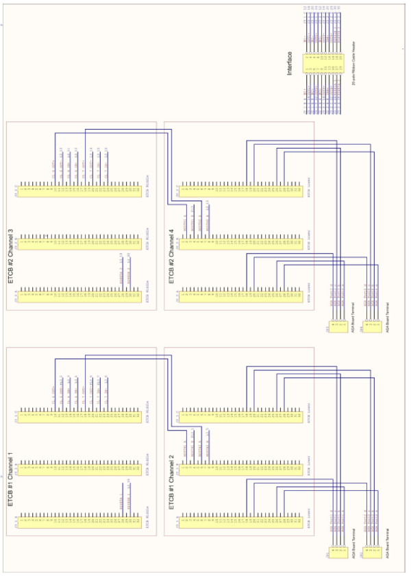
Wiring Diagram for 4 channels
Pin out for ASA ETCB Connectors
Post dialing functions in short form

- ASA calls ACM with ASA-call-back is set (yes)
- ASA extension dials “04 – ACM number”
- ASA is A-extension
- ASA–AC Server receives the call
- ASA extension is disconnected and reconnected from ASA-AC Server
- ASA is now B-extension
- ASA-AC Server dials to ACM
- Post dialing from AC to ASA is possible
- ASA calls ACM with ASA-call-back is not set (no)
- ASA extension dials “04 – ACM number”
- ASA is A-extension
- ASA–AC Server receives the call
- ASA-AC Server dials to ACM
- Post dialing from ACM to ASA is not possible
Technical Data SGA 65008
| Dimension (WxHxD): | 437 x 43 x 249mm, 19” / 1U |
| Operating voltage: | 100-240 VAC |
| Power consumption: | 200W |
| Ethernet connection: | 1 x RJ45 10/100 Mbps |
| Max. distance to AlphaCom: | 100m according to IEEE 802.3 |
| Max. distance to ASACOM: | 100m |
| Audio: | 0 dB, 600 ohms, 300 – 3400 Hz |
| Data protocols: | IP v4, TCP, UDP, HTTP,RTP, RTCP, DHCP, DiffServ, TOS, STENTOFON CCoIP®, ASKNEW |
| Operating temperature range: | 10°C to + 35°C |
| Humidity: | 8% - 90% RH (non-condensing) |
| Weight: | 4.5 kg |
