TFIE Dimensions & Mounting Instructions: Difference between revisions
From Zenitel Wiki
No edit summary |
|||
| (7 intermediate revisions by 2 users not shown) | |||
| Line 7: | Line 7: | ||
|- | |- | ||
|TFIX-x || 346 x 178 x 101 mm || 1.9 kg | |TFIX-x || 346 x 178 x 101 mm || 1.9 kg | ||
|} | |} | ||
| Line 22: | Line 20: | ||
=Opening the enclosure= | =Opening the enclosure= | ||
[[File:TFIE opening 1.PNG|thumb|left| | Loosen the 2 screws securing the front frame to the on-wall box: | ||
[[File:TFIE opening 1.PNG|thumb|left|200px]] | |||
<br style="clear:both;" /> | <br style="clear:both;" /> | ||
[[File:TFIE opening 2.PNG|thumb|left| | Open the enclosure by pulling the front frame out 5 mm, keeping it parallel to the on-wall box. This is necessary to get clearing for the hinges: | ||
[[File:TFIE opening 2.PNG|thumb|left|200px]] | |||
<br style="clear:both;" /> | <br style="clear:both;" /> | ||
Pull the right side of the front frame to fully open the enclosure. Do NOT open the enclosure to the extent that cables between the front and back parts are pulled tight: | |||
[[File:TFIE opening 3.PNG|thumb|left|300px]] | [[File:TFIE opening 3.PNG|thumb|left|300px]] | ||
<br style="clear:both;" /> | <br style="clear:both;" /> | ||
=Mounting the unit= | =Mounting the unit= | ||
'''Preparation for Drilling''' | |||
The four mounting holes in the onwall box are Ø6.4 mm. Distance: 298 x 130 mm. Size of hole to be drilled depends on whether it is wall or column mounting: | |||
[[File:TFIE Mounting 1.PNG|thumb|300px|left]] | |||
<br style="clear:both;" /> | |||
'''Location''' | |||
Make sure there is a clearance of minimum 230 mm on the left for frame movement. | |||
[[File:TFIE Mounting 2.PNG|thumb|400px|left]] | |||
<br style="clear:both;" /> | |||
'''Mounting Plate or Column''' | |||
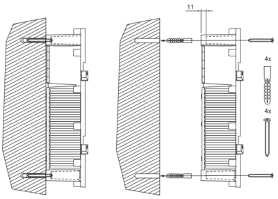
Fix the unit to mounting plate or column with 4 screws that fit the 4 screw holes in each corner of on-wall box (6.4 mm diameter). Use M5 x 20 or 25 with Philips head DIN7985 or Torx. Head diameter: 10 mm. | |||
[[File:TFIE Mounting 3.PNG|thumb|300px|left]] | |||
<br style="clear:both;" /> | |||
'''Wall''' | |||
Fix the unit to the wall with 4 screws that fit the 4 screw holes in each corner of the on-wall box (6.4 mm diameter). Use Panhead – DIN7981 screw for plug or wooden wall. Head diameter: 10.8 B5.5 x 38 or 45 mm. | |||
[[File:TFIE Mounting 4.PNG|thumb|400px|left]] | |||
<br style="clear:both;" /> | |||
'''Mounting Cable Gland''' | |||
Remove two blind plugs and insert one M16 and one M20 cable glands. Make sure to tighten sufficiently to attain IP66 rating for watertightness but be aware of plastic material limitations. | |||
[[File:TFIE Mounting 5.PNG|thumb|400px|left]] | |||
<br style="clear:both;" /> | |||
In order to ensure the required minimum degree of protection, the cable glands must be tightened securely. | |||
Over-tightening can impair the degree of protection and damage the unit. | |||
When tightening the cap nut of a cable gland, a suitable tool shall be used to prevent the gland from twisting. | |||
'''Fastening Front Frame''' | |||
Do NOT use more than 2.5 Nm torque when fastening the 12 screws into the front frame. | |||
[[File:TFIE Mounting 6.PNG|thumb|400px|left]] | |||
<br style="clear:both;" /> | |||
[[Category: Turbine]] | [[Category: Turbine Dimensions & Mounting Instructions]] | ||
Latest revision as of 12:55, 17 October 2016
| Dimensions (WxHxD) | Weight | |
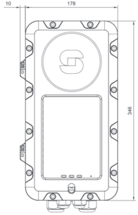
| TFIE-x | 346 x 178 x 101 mm | 1.9 kg |
| TFIX-x | 346 x 178 x 101 mm | 1.9 kg |
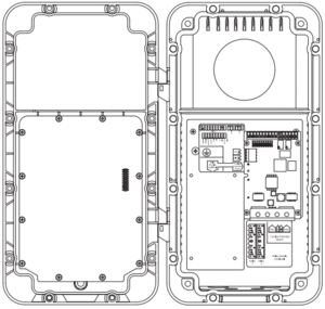
TFIE/TFIX Extended Station Dimensions
Opening the enclosure
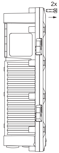
Loosen the 2 screws securing the front frame to the on-wall box:
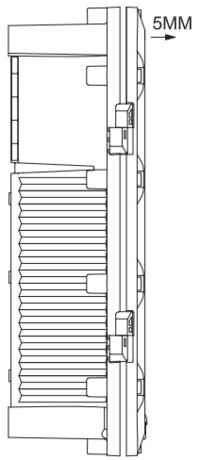
Open the enclosure by pulling the front frame out 5 mm, keeping it parallel to the on-wall box. This is necessary to get clearing for the hinges:
Pull the right side of the front frame to fully open the enclosure. Do NOT open the enclosure to the extent that cables between the front and back parts are pulled tight:
Mounting the unit
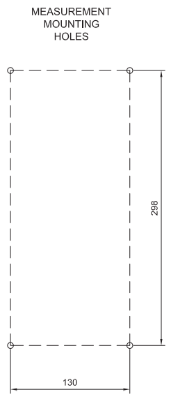
Preparation for Drilling
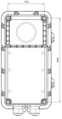
The four mounting holes in the onwall box are Ø6.4 mm. Distance: 298 x 130 mm. Size of hole to be drilled depends on whether it is wall or column mounting:
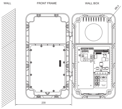
Location
Make sure there is a clearance of minimum 230 mm on the left for frame movement.
Mounting Plate or Column
Fix the unit to mounting plate or column with 4 screws that fit the 4 screw holes in each corner of on-wall box (6.4 mm diameter). Use M5 x 20 or 25 with Philips head DIN7985 or Torx. Head diameter: 10 mm.
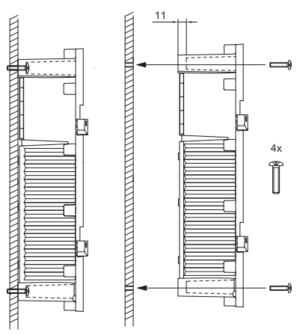
Wall
Fix the unit to the wall with 4 screws that fit the 4 screw holes in each corner of the on-wall box (6.4 mm diameter). Use Panhead – DIN7981 screw for plug or wooden wall. Head diameter: 10.8 B5.5 x 38 or 45 mm.
Mounting Cable Gland
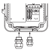
Remove two blind plugs and insert one M16 and one M20 cable glands. Make sure to tighten sufficiently to attain IP66 rating for watertightness but be aware of plastic material limitations.
In order to ensure the required minimum degree of protection, the cable glands must be tightened securely.
Over-tightening can impair the degree of protection and damage the unit.
When tightening the cap nut of a cable gland, a suitable tool shall be used to prevent the gland from twisting.
Fastening Front Frame
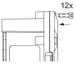
Do NOT use more than 2.5 Nm torque when fastening the 12 screws into the front frame.

