IP Flush Master Gooseneck: Difference between revisions
From Zenitel Wiki
No edit summary |
No edit summary |
||
| Line 10: | Line 10: | ||
* Slide the '''S1''' switch (bottom back of station) to '''EXT''' to activate the external microphone function. | * Slide the '''S1''' switch (bottom back of station) to '''EXT''' to activate the external microphone function. | ||
For board connectors, see [[INCA Master Station Kit Board Connectors]]. | |||
[[File:IP_Master_Gooseneck_Microphone_Installation.PNG]]<br/> | [[File:IP_Master_Gooseneck_Microphone_Installation.PNG]]<br/> | ||
| Line 21: | Line 21: | ||
<br style="clear:both;" /> | <br style="clear:both;" /> | ||
=== | == Related articles == | ||
* [http://www.zenitel.com/product/gooseneck-microphone Additional Documentation on Zenitel.com] | |||
[[Category: INCA Backboxes and accessories]] | [[Category: INCA Backboxes and accessories]] | ||
Revision as of 17:03, 16 March 2017
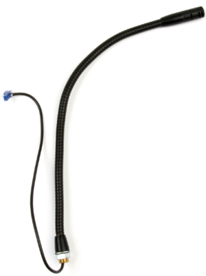
This microphone is for the IP Flush Master Station and the IP Master Station Kit.
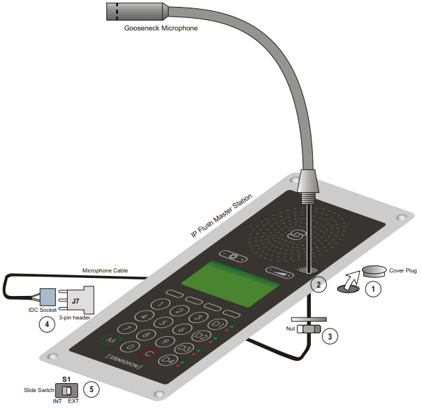
To install the Gooseneck Microphone:
- Remove the cover plug from the opening for the microphone on the front panel.
- Thread the microphone cable through the opening, the lock washer and nut.
- Tighten the nut on the microphone’s threaded stud.
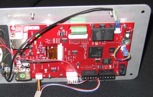
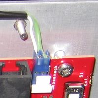
- Insert the microphone’s IDC socket into the upper two pins of the 3-pin header (J7) located at the lower left side of the station. The signal wire (white) should be on the top pin while the ground wire (green) should be on the bottom pin.
- Slide the S1 switch (bottom back of station) to EXT to activate the external microphone function.
For board connectors, see INCA Master Station Kit Board Connectors.
Installing the Gooseneck Microphone


