IP Heavy Duty Connections: Difference between revisions
From Zenitel Wiki
| Line 45: | Line 45: | ||
**Pin 1/2: Connection of external 8 ohm loudspeaker (optional). | **Pin 1/2: Connection of external 8 ohm loudspeaker (optional). | ||
**Pin 3/4: Internal NO relay contact for additional call indication, etc. | **Pin 3/4: Internal NO relay contact for additional call indication, etc. | ||
**Pin 5/6: Connect 24VDC | **Pin 5/6: Connect 24VDC power supply if PoE is not used | ||
* '''P4''': 6-pin plug-on screw terminal for internal connections. | * '''P4''': 6-pin plug-on screw terminal for internal connections. | ||
Revision as of 12:51, 17 March 2017
Main connectors
To access these connectors the frontplate must be removed.
| LAN | 10/100 Mbps RJ-45 port for LAN (uplink) connection. Supports PoE (802.3af). Draws power from either spare line or signal line. |
| AUX | 10/100 Mbps RJ-45 ports for auxiliary equipment such as PC and IP camera. |
| Input/Output | Pluggable screw terminal |
| Local Power | Plugable screw terminal, 19-27 VDC Idle 4W, max. 8W |
Power Supply
The IP Heavy Duty Station supports Power over Ethernet (PoE, IEEE 802.3 a-f) where power can be drawn from either the spare line or signal line.
If PoE is not available, the IP Substation can be connected to a 24 VDC local power supply.
Network Connection
There are two RJ45 ports on the IP Heavy Duty stations:
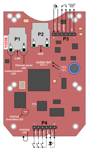
- LAN port (P1): for connecting to the network and the AlphaCom XE Audio Server.
- AUX port (P2): for connecting to auxiliary equipment such as a PC or IP Camera.
Input/Output Connections
There are I/O connection options for all IP Substations. These I/O connections include:
- 3 digital inputs (P4):
- Input 1 = PTT from headset, and for restoring factory default
- Input 2 = Call button no.2 or logical input (optional)
- Input 3 = Hookswitch
- 1 relay output (P3)
- 1 logical output (TP9)
- 1 Line out (TP1/2): Audio output to handset speaker (0dBm 600ohm balanced)
Connections
There are four connectors on the IP heavy Duty station PCB: P1-P4.
- P1 RJ45 LAN port is for connecting to the data network
- P2: RJ45 AUX port is for connecting to auxiliary equipment such as a PC
- P3: 6-pin plug-on screw terminal for external connections.
- Pin 1/2: Connection of external 8 ohm loudspeaker (optional).
- Pin 3/4: Internal NO relay contact for additional call indication, etc.
- Pin 5/6: Connect 24VDC power supply if PoE is not used
- P4: 6-pin plug-on screw terminal for internal connections.
- Pin 1/4: Input for PTT from headset and restoring Factory Default Setting.
- Pin 2/4: Call button no. 2 or logical input (optional).
- Pin 3/4: Connected to hook-switch (reed-switch)
- Pin 5/6: Station LED for call and message info. (Pin 6 is positive.)
- TP1/2: Audio output to handset speaker (0 dB, 600 ohm balanced).
For more details see INCA Substation Board Connectors.


