Substation Kit - 1007102000: Difference between revisions
From Zenitel Wiki
No edit summary |
No edit summary |
||
| (11 intermediate revisions by 2 users not shown) | |||
| Line 1: | Line 1: | ||
{{A}} | |||
[[Image:1007102000.PNG|thumb|350px|Substation Kit]] | [[Image:1007102000.PNG|thumb|350px|Substation Kit]] | ||
The '''Substation Kit - 1007102000''' can be used to design and manufacture special stations for the AlphaCom. The Substation Kit is | The '''Substation Kit - 1007102000''' can be used to design and manufacture special stations for use with the AlphaCom server. The Substation Kit is connected to an [[ASLT]] subscriber line. | ||
== | ==Highlights== | ||
* Complete kit to manufacture a customized substation for the AlphaCom XE | * Complete kit to manufacture a customized substation for the AlphaCom XE | ||
* Vandal resistant call button | * Vandal resistant call button | ||
| Line 10: | Line 11: | ||
* External or extra call button option | * External or extra call button option | ||
== | ==The Substation Kit== | ||
The kit consists of: | The kit consists of: | ||
* Substation board | * Substation board | ||
| Line 17: | Line 18: | ||
* Tamperproof button | * Tamperproof button | ||
=== | ===Substation Board=== | ||
The A100C01307 station board, nylon screws and spacers and packaging. | The A100C01307 station board, nylon screws and spacers and packaging. | ||
==== | ====Connection details==== | ||
*The microphone gain is adjusted by potentiometer RP1 | *The microphone gain is adjusted by potentiometer RP1 | ||
*The loudspeaker volume is adjusted by potentiometer RP2 | *The loudspeaker volume is adjusted by potentiometer RP2 | ||
[[Image:sub.JPG|thumb|left|500px| | [[Image:sub.JPG|thumb|left|500px|Dimensions and connection Diagram]] | ||
<br style="clear:both;" /> | <br style="clear:both;" /> | ||
'' | ''Connectors:'' | ||
{|border="1" | {|border="1" | ||
!style=background:#ffdead; | Connector | !style=background:#ffdead; | Connector-pin | ||
!style=background:#ffdead; | Function | !style=background:#ffdead; | Function | ||
|- | |- | ||
|J4-1 ||Electret microphone (positive) | |align="center"| J4-1 ||Electret microphone (positive) | ||
|- | |- | ||
|J4-2 ||Electret Microphone (negative) | |align="center"| J4-2 ||Electret Microphone (negative) | ||
|- | |- | ||
|J4-3<br>J4-4 || Loudspeaker, no volume control<br> | |align="center"| J4-3<br>J4-4 || Loudspeaker, no volume control<br> | ||
|- | |- | ||
|J4-2<br>J5-2 || Dynamic close talk microphone<br> | |align="center"| J4-2<br>J5-2 || Dynamic close talk microphone<br> | ||
|- | |- | ||
|J4-5<br>J5-1 || ID+M-button<br> | |align="center"| J4-5<br>J5-1 || ID+M-button<br> | ||
|- | |- | ||
|J5-3<br>J5-4 || ID-button<br> | |align="center"| J5-3<br>J5-4 || ID-button<br> | ||
|- | |- | ||
|J6-1 || d-wire | |align="center"| J6-1 || d-wire | ||
|- | |- | ||
|J6-2 || c-wire | |align="center"| J6-2 || c-wire | ||
|- | |- | ||
|J6-3 || b-wire | |align="center"| J6-3 || b-wire | ||
|- | |- | ||
|J6-4 || a-wire | |align="center"| J6-4 || a-wire | ||
|- | |- | ||
|J7-1 <br> J7-2 || Loudspeaker with volume control<br> | |align="center"| J7-1<br>J7-2 || Loudspeaker with volume control<br> | ||
|- | |- | ||
|J7-3 <br>J7-4 || Status LED. J7-3 Positive, J7-4 negative. | |align="center"| J7-3<br>J7-4 || Status LED. J7-3 Positive, J7-4 negative. | ||
|} | |} | ||
{{note|A LED or a piece of wire (short) '''must''' be connected between J7-3 and J7-4, else the microphone will not work. }} | |||
===== | The shunt S1 is for Private/Open mode: | ||
* Shorted = Private | |||
* Open = Open (Default) | |||
====Mechanical mounting==== | |||
The circuit board should be mounted with the nylon screws and spacers due to ESD protection. You can use weld nuts with the size of M3.0x5.0x6.0 fastened to the front plate for the screws. | The circuit board should be mounted with the nylon screws and spacers due to ESD protection. You can use weld nuts with the size of M3.0x5.0x6.0 fastened to the front plate for the screws. | ||
=== | ===Loudspeakers=== | ||
Two loudspeakers are included with the kit: | Two loudspeakers are included with the kit: | ||
* 2.5" 45 ohms waterproof loudspeaker (ENAUD20875) | * 2.5" 45 ohms waterproof loudspeaker (ENAUD20875) | ||
| Line 71: | Line 76: | ||
<br style="clear:both;" /> | <br style="clear:both;" /> | ||
=== | ===Electret microphone=== | ||
Condencer microphone and absorbing baffle. For mounting considerations, see subarticle [[#Acoustical Considerations|Acoustical Considerations]] | Condencer microphone and absorbing baffle. For mounting considerations, see subarticle [[#Acoustical Considerations|Acoustical Considerations]] | ||
=== | ===Tamperproof button=== | ||
Tamperproof button and wires. To mount the button, drill a hole in the front plate with diameter 20 mm. The button will build 25mm into the station. | Tamperproof button and wires. To mount the button, drill a hole in the front plate with diameter 20 mm. The button will build 25mm into the station. | ||
== | ==Acoustical Considerations== | ||
The most important acoustical issues to be aware of when designing a new station is: | The most important acoustical issues to be aware of when designing a new station is: | ||
| Line 101: | Line 106: | ||
*To do a really good acoustical design requires much work and experience. The most important criteria is of course the subjective: To fulfill the customer’s needs. | *To do a really good acoustical design requires much work and experience. The most important criteria is of course the subjective: To fulfill the customer’s needs. | ||
== | ==EMC Considerations== | ||
=== | ===Regulations=== | ||
The basic requirement is that the equipment must comply with the EMC directive 89/336/EEC. The standards used to determine compliance is EN50081-1/EN55022 class B for emission and EN 50082-1 for immunity (domestic, office, light industry). | The basic requirement is that the equipment must comply with the EMC directive 89/336/EEC. The standards used to determine compliance is EN50081-1/EN55022 class B for emission and EN 50082-1 for immunity (domestic, office, light industry). | ||
| Line 110: | Line 115: | ||
=== | ===Declaration of Conformity=== | ||
| Line 116: | Line 121: | ||
<br> | <br> | ||
=== | ===Practical issues=== | ||
All the electronic parts which are used in the stations have already been tested for EMC compliance at different laboratories. Generally it is no guaranty for system compliance that the individual parts have been tested for compliance. However, if the assembly guidelines set up by Zenitel is followed, we have experienced that compliance is achieved. | All the electronic parts which are used in the stations have already been tested for EMC compliance at different laboratories. Generally it is no guaranty for system compliance that the individual parts have been tested for compliance. However, if the assembly guidelines set up by Zenitel is followed, we have experienced that compliance is achieved. | ||
=== | ==Additional Documentation == | ||
* [http://www.zenitel.com/product/substation-kit Additional Documentation on Zenitel.com] | |||
[[Category: Analogue 4-wire Stations]] | [[Category: Analogue 4-wire Stations]] | ||
Latest revision as of 12:57, 31 August 2018
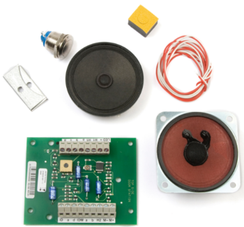
The Substation Kit - 1007102000 can be used to design and manufacture special stations for use with the AlphaCom server. The Substation Kit is connected to an ASLT subscriber line.
Highlights
- Complete kit to manufacture a customized substation for the AlphaCom XE
- Vandal resistant call button
- Superb audio quality (10 kHz)
- Advanced supervision functions
- External or extra call button option
The Substation Kit
The kit consists of:
- Substation board
- Two loudspeakers
- Electret microphone
- Tamperproof button
Substation Board
The A100C01307 station board, nylon screws and spacers and packaging.
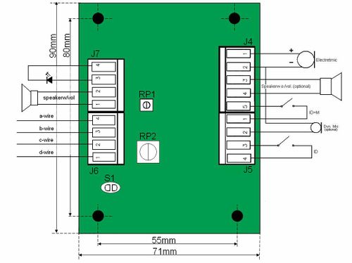
Connection details
- The microphone gain is adjusted by potentiometer RP1
- The loudspeaker volume is adjusted by potentiometer RP2
Connectors:
| Connector-pin | Function |
|---|---|
| J4-1 | Electret microphone (positive) |
| J4-2 | Electret Microphone (negative) |
| J4-3 J4-4 |
Loudspeaker, no volume control |
| J4-2 J5-2 |
Dynamic close talk microphone |
| J4-5 J5-1 |
ID+M-button |
| J5-3 J5-4 |
ID-button |
| J6-1 | d-wire |
| J6-2 | c-wire |
| J6-3 | b-wire |
| J6-4 | a-wire |
| J7-1 J7-2 |
Loudspeaker with volume control |
| J7-3 J7-4 |
Status LED. J7-3 Positive, J7-4 negative. |

|
A LED or a piece of wire (short) must be connected between J7-3 and J7-4, else the microphone will not work. |
The shunt S1 is for Private/Open mode:
- Shorted = Private
- Open = Open (Default)
Mechanical mounting
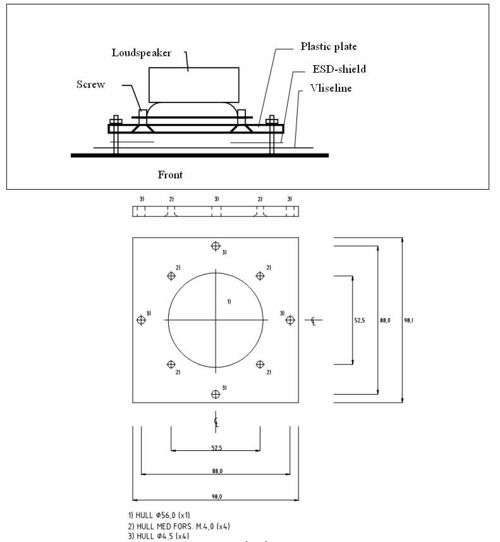
The circuit board should be mounted with the nylon screws and spacers due to ESD protection. You can use weld nuts with the size of M3.0x5.0x6.0 fastened to the front plate for the screws.
Loudspeakers
Two loudspeakers are included with the kit:
- 2.5" 45 ohms waterproof loudspeaker (ENAUD20875)
- 64 mm (diameter) 50 ohms 1W paper loudspeaker (ENAUD20900)
- Fastening plate, ESD-shield, screws, nuts, 0,3m cable and vliseline (protective cloth in dark gray)
Electret microphone
Condencer microphone and absorbing baffle. For mounting considerations, see subarticle Acoustical Considerations
Tamperproof button
Tamperproof button and wires. To mount the button, drill a hole in the front plate with diameter 20 mm. The button will build 25mm into the station.
Acoustical Considerations
The most important acoustical issues to be aware of when designing a new station is:
- The loudspeaker.
- Frequency response: With the loudspeaker one should try to achieve a frequency response quite flat, but with a slight emphasis in the mid frequency area (around 800Hz). The frequency response is affected by the loudspeaker itself, and by the mechanical design of the station.
- Chamber (the area behind the loudspeaker): The chamber can be a separate box behind the loudspeaker, or it can be the station housing itself. The shape and size of the chamber will influence on the sound from the loudspeaker. If the rear side of the loudspeaker is not acoustical shielded from the front, sound waves from the rear can affect the frequency response in the listeners spot. The chamber should if possible have rounded edges to prevent standing waves (resonance), and it should be filled with a sound absorbing material to further damp standing waves which will influence on the speaker diaphragm and so on the sound reproduction. A reason to use a separate box for the loudspeaker is to reduce the acoustical coupling between the loudspeaker and microphone.
- The grille on the front plate is more a cosmetic issue as long as there are enough opening (approx. 50%). The grille should cover the loudspeaker area.
- The microphone.
The mounting of the microphone is quite critical concerning:
- Shielding: It should mechanically be shielded from the loudspeaker. This is done by mounting it in an absorbing material, and if possible not directly to the same front plate as the loudspeaker.
- Frequency response: The microphone should also be mounted as close to the front plate as possible. The space between the split in the front plate and the microphone can affect the frequency response. Also the split (or splits) should be longer than the diameter of the microphone.
- Non-linear effects: There must be no loose parts that can vibrate as this will cause distorting sound. A simple measurement method is to do a frequency sweep with quite loud volume, and then listen do detect problems.
- Acoustical coupling: If the acoustical coupling between the loudspeaker and microphone becomes to high the duplex algorithm in the exchange will not have an optimal performance. You should try to place the microphone and loudspeaker as far apart as possible. To verify that the duplex will function acceptable one should do a counting test (the person at one of the locations says ‘One’, the person at the second location says ‘Two’ etc.) and if possible with some background noise.
- To do a really good acoustical design requires much work and experience. The most important criteria is of course the subjective: To fulfill the customer’s needs.
EMC Considerations
Regulations
The basic requirement is that the equipment must comply with the EMC directive 89/336/EEC. The standards used to determine compliance is EN50081-1/EN55022 class B for emission and EN 50082-1 for immunity (domestic, office, light industry).
Declaration of Conformity
It is the organization/person who brings the product to market that is responsible for the EMC compliance of an assembled product. Therefore a Conformity declaration must be issued stating that the product (“name”) conforms to relevant Directive(s), with possible references to harmonized standards and test reports as supporting evidence. The document must be signed by a responsible person.
Practical issues
All the electronic parts which are used in the stations have already been tested for EMC compliance at different laboratories. Generally it is no guaranty for system compliance that the individual parts have been tested for compliance. However, if the assembly guidelines set up by Zenitel is followed, we have experienced that compliance is achieved.


