Serial port pinout: Difference between revisions
From Zenitel Wiki
No edit summary |
m (40 revisions imported) |
||
| (28 intermediate revisions by 3 users not shown) | |||
| Line 1: | Line 1: | ||
The AlphaCom XE exchanges has two serial ports. In [[AlphaCom XE20]] and [[AlphaCom XE26|XE26]] they are available on RJ45 connectors. In [[AlphaCom XE7]] the serial port 0 is on a 9 pin DSUB connector, and the serial port 1 is on a RJ45 connector. | |||
The serial port 0 is RS232 only, the serial port 1 can be RS232, RS422 or RS485. | The serial port 0 is RS232 only, the serial port 1 can be RS232, RS422 or RS485. | ||
=== Pinout of the RJ45 connector === | |||
[[Image:RJ45 pinout.jpg|left|RJ45 pinout]] | |||
<br style="clear:both;" /> | |||
{|border="1" | {|border="1" | ||
|- | |- | ||
!style="background:#ffdead;" width="90pt"; colspan = 2|RJ45 pinout | !style="background:#ffdead;" width="90pt"; colspan = 2|RJ45 pinout | ||
|- | |- | ||
|RS232||3 = TX<br | |RS232||3 = TX<br />6 = RX<br /> 4&5 = GND | ||
|- | |- | ||
|RS422||1 = RX-<br | |RS422||1 = RX-<br />2 = RX+<br />7 = TX-<br />8 = TX+ | ||
|- | |- | ||
|RS485||1/7 = Data - <br | |RS485||1/7 = Data - <br /> 2/8 = Data+ | ||
|- | |- | ||
|} | |} | ||
<br | <br /><br /> | ||
Adaptor cable from RJ-45 to 9-pin Female D-SUB | === Pinout of the 9-pin D-SUB connector === | ||
[[File:DSUB Pinout.PNG|left|thumb|200px|9-pin DSUB pinout]] | |||
<br style="clear:both;" /> | |||
===Adaptor cable from RJ-45 to 9-pin Female D-SUB=== | |||
{|border="1" | {|border="1" | ||
|- | |- | ||
| Line 26: | Line 32: | ||
|3||2 | |3||2 | ||
|- | |- | ||
|5||5 | |4&5||5 | ||
|- | |- | ||
|6||3 | |6||3 | ||
| Line 32: | Line 38: | ||
|} | |} | ||
<br><br> | |||
== AlphaCom - RIO cabling == | |||
[[RIO]] | Cabling between the [[RIO]] unit and AlphaCom XE using multidrop RS485: | ||
<pre> | <pre> | ||
AlphaCom RIO #1 RIO #n | AlphaCom RIO #1 RIO #n | ||
Serial | Serial port 15 pin DSUB 15 pin DSUB | ||
RJ45 | RJ45 | ||
1 -----------------+-- 9 --+----------------+-- 9 | 1 -------------------------+-- 2 --+----------------+-- 2 | ||
| | | | |||
--- 4 --- --- 4 | |||
2 -------------------------+-- 9 --+----------------+-- 9 | |||
| | | | |||
--- 11--- --- 11 | |||
5 ---Gnd (optional)--------+-- 5 --+----------------+-- 5 | |||
</pre> | </pre> | ||
In the 15 pin DSUB of the RIO unit pin 2 & 4 and 9 & 11 must be connected together. | In the 15 pin DSUB of the RIO unit pin 2 & 4 and 9 & 11 must be connected together. | ||
[[Category:AlphaCom | The GND connection between AlphaCom and RIO in RS485 mode is normally not necessary. In general on RS485 links, the connection of a third wire (GND) between the source and receiver may be done to limit the common mode voltage that can be impressed on the receiver inputs. | ||
Note that when using RS485, the switch S601-8 on the AMC-IP must be set to RS422 positon, and two jumpers must be moved from RS422 to RS485 position. These jumpers are located on the AMC-IP filter board for XE20 and 26, and on the backplane of the AlphaCom XE7. On the AlphaCom XE1 you need to open the cover to access the jumpers. | |||
Cabling between the RIO unit and AlphaCom XE using point to point RS232: | |||
<pre> | |||
AlphaCom RIO | |||
Serial port 9 pin DSUB | |||
RJ45 | |||
3 (TX) ---------------+-- 2 --+ | |||
6 (RX) ---------------+-- 3 --+ | |||
5 (GND) --------------+-- 5 --+ | |||
</pre> | |||
[[Category:AlphaCom Hardware]] | |||
Latest revision as of 13:24, 5 February 2018
The AlphaCom XE exchanges has two serial ports. In AlphaCom XE20 and XE26 they are available on RJ45 connectors. In AlphaCom XE7 the serial port 0 is on a 9 pin DSUB connector, and the serial port 1 is on a RJ45 connector.
The serial port 0 is RS232 only, the serial port 1 can be RS232, RS422 or RS485.
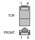
Pinout of the RJ45 connector
| RJ45 pinout | |
|---|---|
| RS232 | 3 = TX 6 = RX 4&5 = GND |
| RS422 | 1 = RX- 2 = RX+ 7 = TX- 8 = TX+ |
| RS485 | 1/7 = Data - 2/8 = Data+ |
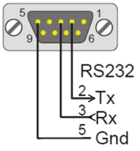
Pinout of the 9-pin D-SUB connector
Adaptor cable from RJ-45 to 9-pin Female D-SUB
| RJ45 - AlphaCom E | 9 p Female DSUB |
|---|---|
| 3 | 2 |
| 4&5 | 5 |
| 6 | 3 |
AlphaCom - RIO cabling
Cabling between the RIO unit and AlphaCom XE using multidrop RS485:
 AlphaCom               RIO #1                  RIO #n
 Serial port          15 pin DSUB             15 pin DSUB
  RJ45

   1 -------------------------+-- 2 --+----------------+-- 2
                              |       |                |
                              --- 4 ---                --- 4

   2 -------------------------+-- 9 --+----------------+-- 9
                              |       |                |
                              --- 11---                --- 11

   5 ---Gnd (optional)--------+-- 5 --+----------------+-- 5
In the 15 pin DSUB of the RIO unit pin 2 & 4 and 9 & 11 must be connected together.
The GND connection between AlphaCom and RIO in RS485 mode is normally not necessary. In general on RS485 links, the connection of a third wire (GND) between the source and receiver may be done to limit the common mode voltage that can be impressed on the receiver inputs.
Note that when using RS485, the switch S601-8 on the AMC-IP must be set to RS422 positon, and two jumpers must be moved from RS422 to RS485 position. These jumpers are located on the AMC-IP filter board for XE20 and 26, and on the backplane of the AlphaCom XE7. On the AlphaCom XE1 you need to open the cover to access the jumpers.
Cabling between the RIO unit and AlphaCom XE using point to point RS232:
 AlphaCom                   RIO
 Serial port             9 pin DSUB
  RJ45

   3 (TX) ---------------+-- 2 --+

   6 (RX) ---------------+-- 3 --+

   5 (GND) --------------+-- 5 --+


