LenelS2 OnGuard - IC-EDGE Integration: Difference between revisions
From Zenitel Wiki
No edit summary |
|||
| Line 4: | Line 4: | ||
This article describes the installation and operation between Zenitel’s [[:category:IC-EDGE System|IC-EDGE System]] and LenelS2 OnGuard. | This article describes the installation and operation between Zenitel’s [[:category:IC-EDGE System|IC-EDGE System]] and LenelS2 OnGuard. | ||
For integration between LenelS2 OnGuard and the ICX | For integration between LenelS2 OnGuard and the ICX-AlphaCom system, see [[LenelS2 OnGuard - ICX-AlphaCom Integration|here]]. | ||
__TOC__ | __TOC__ | ||
=== IC-EDGE devices=== | === IC-EDGE devices=== | ||
Latest revision as of 15:12, 15 August 2022
Introduction
This article describes the installation and operation between Zenitel’s IC-EDGE System and LenelS2 OnGuard.
For integration between LenelS2 OnGuard and the ICX-AlphaCom system, see here.
IC-EDGE devices
Supported Vingtor-Stentofon devices
The devices in the list below can be used within an OnGuard integrated system
- Turbine TCIS-1/2/3/4/5/6/C1
- Turbine Video TCIV-2/3/5/6
- IP-Flush Master
- IP Desktop Masters
- IP Clean Room / O.R. Master
- ITSV-1
- VS-Client
- TFIE-1/2
- TKIE-1/2/3
- TMIS-1/2
- TFIX-1/2
- IP-speakers ELSIR-10C and ELSII-10H
- Exigo Amplifiers ENA2100/2200/2400
- Exigo Call Panels ECPIR
Edge Controller
The devices in the list below can be configured as Edge Controller within an OnGuard integrated system
- Turbine TCIS-1/2/3/4/5/6
- TKIS-2
- TFIE-1/2
- TKIE-1/2/3
- TMIS-1/2
- IP-speakers ELSIR-10C and ELSII-10H
Installation and Configuration
It is assumed that the reader is familiar with IC-EDGE™ and OnGuard® and knows how to install and configure both these systems for what can be considered ‘standard operation’, see Prerequisites.
There are a few capabilities available in the integrated system that require some special configuration. These are described in the rest of the chapter.
Prerequisites
- OnGuard 7.4 or newer installed and configured on a compatible Operating System
- Devices have been upgraded:
- IC-EDGE devices to version 5.0.3.0 or later
- INCA devices: Minimum version 2.10.3.0
- The IC-EDGE system has been configured and the system is working properly – directory numbers must be in the range 1-32766; no leading ‘0’ can be used.
Licensing
OnGuard requires the following license:
- Maximum Number of Intercom Exchanges (SWG-1340)
It is possible to connect multiple IC-EDGE systems to OnGuard. This requires as many SWG-1340 licenses as the number of connected IC-EDGE systems, one per Edge Controller.
The Edge Controller does not require any licenses from Zenitel for integration with OnGuard.
Installation
Install Accessory Add on
The Accessory Add on can be downloaded from the LenelS2 download area. It is listed as 'x.x Accessory Add-On for Zenitel IC-EDGE™ System y.y.y with an msi installation file 'x.x Accessory Add-On for Zenitel IC-EDGE System.msi' Install ‘x.x Accessory Add-On for Zenitel IC-EDGE System.msi’
- x.x denotes the OnGuard version for which the Accessory Add-On is intended
- y.y.y denotes the version of the Add-On.
OnGuard configuration
Define the Edge Controller
Under ‘Additional Hardware’, select ‘Intercom Devices …’ to define the Edge Controller, additional intercom stations and intercom functions.
Define the Edge Controller connection in the TAB ‘Intercom Devices’
- Name: Enter an appropriate name, for instance 'Edge'
- Connection type IPv4
- IP-address: the IP address of the Edge Controller
- Port: 50004 (The use of port 50004 is mandatory. Entering any other port number will cause the integration not to work)
Define Intercom Stations
Define intercom stations in the TAB ‘Intercom Stations’:
- All physical intercom stations in the system
- VS-Client softclients
- All Group calls in the system
- The group call ‘Answer code’ (by default 99)
- Voice messages, see the paragraph Audio messages
Group calls, the group call answer code and voice messages are defined in this way solely to be able to visualize the use of them in Alarm Monitoring and to be able to link them as actions to events in Global I/O.
Define maps and place the intercom icons on those maps as appropriate. It is advised not to place icons related to non-intercom stations on the maps.
Intercom functions
Define intercom functions in the TAB ‘Intercom functions’, see the paragraph Door opening.
Default intercom station
To be able to use the function ‘Call Intercom’ from the Alarm Monitoring GUI, a default operator station for a zone must be defined.
- In System Administration, navigate to ‘Monitoring/Monitoring Zones …’
- Click Add
- Select a Monitoring Zone
- Under ‘Intercom Station/Place calls from:’ select an intercom station from the drop down list
- Click OK
Intercom stations must already have been defined in System Administration.
Specific configuration of IC-EDGE devices
Audio messages
Audio messages need to be setup on each device that will use them. Each device needs to be set in ‘Advanced configuration mode’, see paragraph Advanced configuration mode, to be able to do this.
- Log in into each device
- Navigate to ‘SIP Configuration/Audio Messages’
- Upload all audio messages that need to be configured on each particular device
- Configure each message in the list as following:
- Set ‘Event’ to ‘Call’
- Set Option to ‘Call Ended’/’Outgoing’/’Speaker’/’One Time’ and assign it a directory number, in the example below this is 77
If the same audio messages are used on multiple IC-EDGE devices, then make certain that they are all setup in the same way.
In OnGuard, each audio message must be defined as an ‘Intercom station’. As it is not a physical intercom, such a dummy-station shall not be placed as an icon on a map.
The main purpose of defining audio messages in this way is to use them as part of a definition in Global I/O, for instance to send an audio message as an action on an intrusion event.
Door opening
When a guard is in conversation with an IC-EDGE device at a door, it is possible to open the related door by pressing digit 6 on the intercom keypad. This is an operation with which many people are familiar, as it is the standard relay-trigger command for Zenitel systems. Normally such an action would operate a relay inside the IC-EDGE device to directly operate the door lock.
When IC-EDGE is integrated with OnGuard, pressing digit 6 should not operate a relay on the IC-EDGE device, but rather send a data command to OnGuard, which can then be used by Global I/O to operate the door lock.
IC-EDGE devices do not require specific configuration for this function.
In OnGuard, define an Intercom Function as following:
- Description: Door opening
- Parameter: 6
In Global I/O, define the door station as the station that sends digit 6, not the operator station. This is so that in Global I/O the door station (input event) can be associated with a door (output action).
ITSV-1, ITSV-2, ITSV-3
Alarm Monitoring allows an operator to right click on a device to display an extended menu list. One of the menu items available for IC-EDGE device is ‘Place Call…’
When the device is an ITSV-1/2/3, the ITSV-1/2/3 must be configured to accept such a command.
- Log in into the ITSV-1/2/3 web page
- Navigate to 'Account/Account 1/SIP Settings' or 'Account/Account 1/Advanced Settings' depending on the type and make the following settings:
- Allow Unsolicited REFER: Enabled
To reduce the time that it will take to detect and display a connection error it is necessary to reduce the registration time-out:
- Navigate to Account/Account 1/SIP Settings and make the following settings:
- Register Expiration (m): 1
- Click Save
- At the top of the page, click ‘Apply’
Operation
Commands from the GUI
Users have the ability to execute the following commands (Intercom Right-click Options):
- Place call: displays a dialog box where you enter the station number you are calling to. IC-EDGE does not use the priority setting, it will be ignored
- Cancel Call: cancels the intercom call
- Call Intercom: places a call using the default intercom station for the zone, see paragraph Default intercom station
Visualization
In Alarm Monitoring, the following messages are displayed related to intercom station status changes:
- Call Established – parameters: Originating station and called station
- Call Disconnected – parameters: Originating station and called station
- Call to a Private Subscriber – parameters: Originating station and called station
- Call to a Busy Subscriber – parameters: Originating station and called station
- Call Queued – parameters: Originating station and called station
- Hold – parameters: Station which is placed on hold
- Retrieved as Call Established – parameters: Station of which is the held call is re-established
- Intercom Function; followed by the defined intercom function
In Alarm Monitoring, the following messages are displayed related to intercom system error messages:
- Intercom Exchange Failure – Intercom Error
- Intercom Exchange Failure – Intercom OK
- Edge Controller is down
- Edge Controller is up
Global I/O
Through the linkage server, the following intercom functions can be triggered:
- Place call
- Cancel
For example, place call could be used to start a voice message on a station triggered by an event somewhere else in the system, for instance intrusion detection. This is automated, and does not require an operation from the guard.
By ‘Intercom Function’, it is possible to define the following sub-events:
- Open door
Through the linkage server, it is possible to link an event in IC-EDGE to an action in OnGuard:
- During a call between an operator and a caller at a door station, the operator presses digit ‘6’ on the keypad
- The resulting event in OnGuard will trigger an action: Pulse Door Unlock
OnGuard Maps
All intercom devices that exist in OnGuard Alarm Monitoring can effectively be placed on a map where they can be monitored.
Note: On more information on associating devices with maps, refer to the MapDesigner User Guide that can be provided by LenelS2.
Icons in maps have the following appearances depending on intercom station statuses:
- Idle
- Busy
- InQueue
- Connected: Station is in a conversation with another station
- LineError: A line error to the station has been detected
- Offline: The station is off line; The state is shown when the Communication Server is not running, all station icons will show the Offline state
General information
Default username/password
IC-EDGE web interface credentials are by default admin/alphaadmin for username/password.
Advanced configuration mode
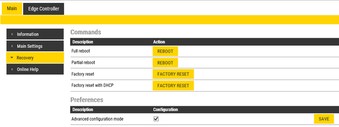
When logging in into the web page of an IC-EDGE device, the available webpages will not show all parameters which can be configured. To setup just a few special functions, for instance voice messaging, the IC-EDGE devices need to be put into ‘Advanced configuration mode’.
- Login into the web pages of the IC-EDGE device
- Navigate to ‘Main/Recovery’
- In the field ‘Advanced configuration mode’ enter the offline password, which by default is ‘1851’
- Enable ‘Configuration’ and click ‘Save’
- Click ‘Reload
Firewall
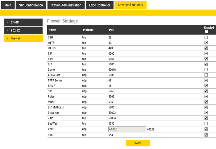
The Edge Controller communicates with OnGuard via TCP-port 50004. This port is by default open. In case of connection problems, it should be checked whether this port is open. The Edge Controller needs to be in ‘Advanced configuration mode’.
- Login into the IC-EDGE device
- Navigate to ‘Advanced Network/Firewall’
- Make certain that port 50004 is enabled; if not, enable the port and click ‘Save’
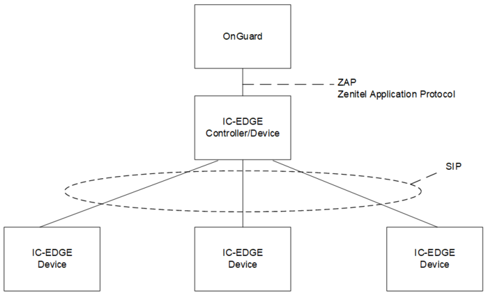
System topology
Limitations
OnGuard defines intercom directory numbers as integers; the supported range in the OnGuard-IC-EDGE integration is 1-32766. Directory numbers with a leading ‘0’ should not be used inside IC-EDGE.


