TEIV Dimensions & Mounting Instructions: Difference between revisions
From Zenitel Wiki
(Created page with "{{AEIS}} {|border="1" |width="250px"| |width="250px"|'''Dimensions (WxHxD)''' |width="150px"|'''Weight''' |- |TEIV-1+ || 120 x 305 x 72 mm || 1.08 kg |- |TEIV-4+ || 120...") |
No edit summary |
||
| Line 5: | Line 5: | ||
|width="150px"|'''Weight''' | |width="150px"|'''Weight''' | ||
|- | |- | ||
|TEIV-1+ || 120 x 305 x 72 mm || 1.08 kg | |[[TEIV-1+]] || 120 x 305 x 72 mm || 1.08 kg | ||
|- | |- | ||
|TEIV-4+ || 120 x 305 x 70 mm || 1.05 kg | |[[TEIV-4+]] || 120 x 305 x 70 mm || 1.05 kg | ||
|- | |- | ||
|} | |} | ||
Revision as of 07:47, 27 September 2023
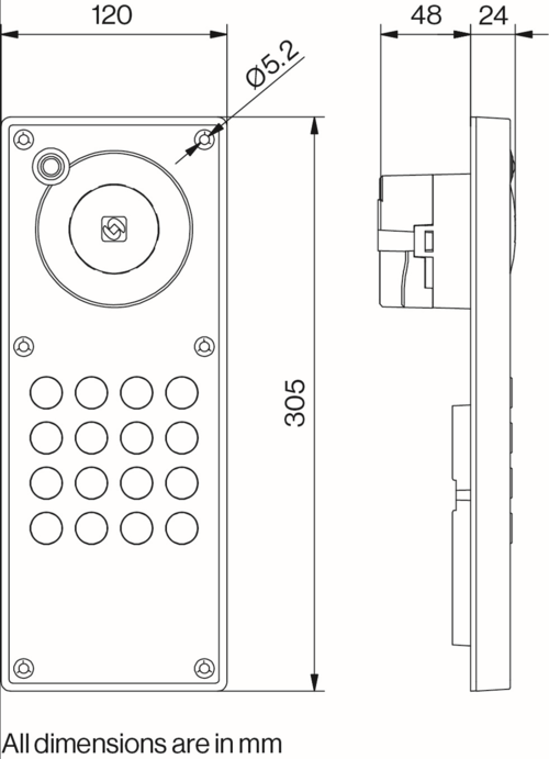
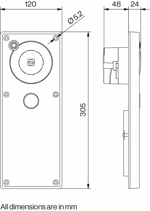
| Dimensions (WxHxD) | Weight | |
| TEIV-1+ | 120 x 305 x 72 mm | 1.08 kg |
| TEIV-4+ | 120 x 305 x 70 mm | 1.05 kg |
TEIV-1+ Station Dimensions
TEIV-4+ Extended Station Dimensions
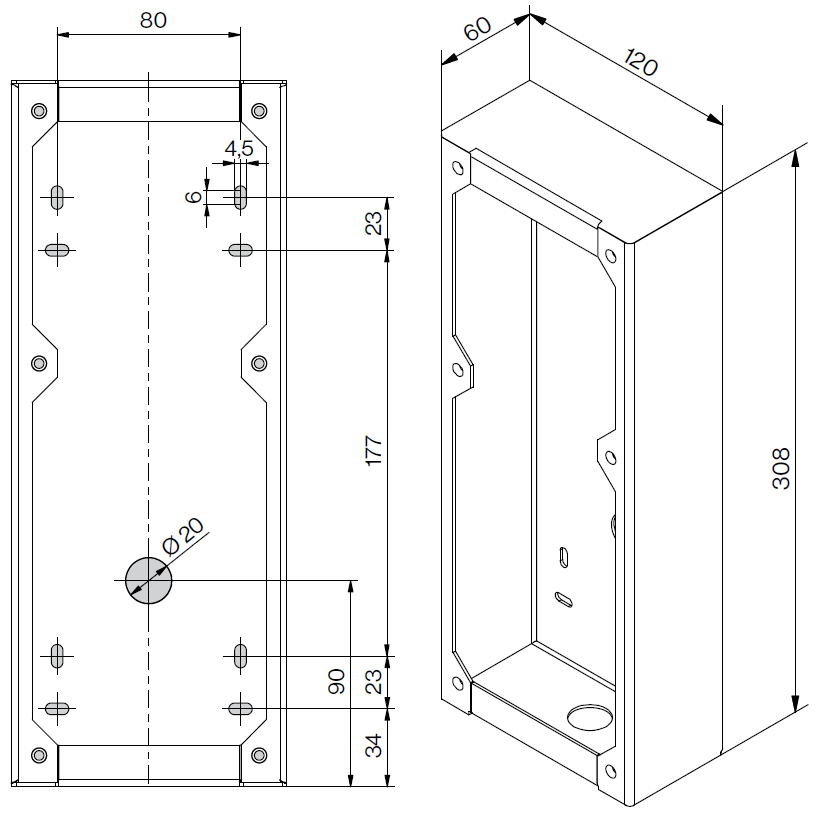
Onwall Surface Mounting
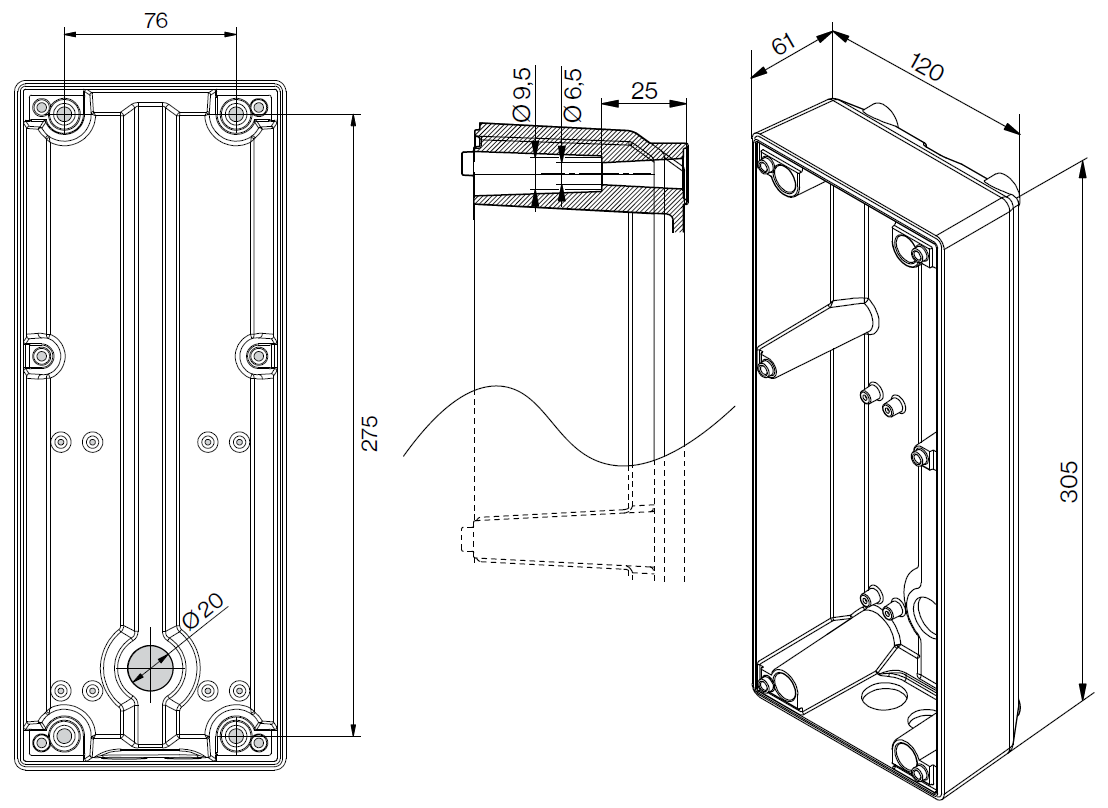
On-Wall Surface Mount Back Box - TA-33
- Mounting holes are to be drilled as shown in the figure.
- Max. recommended screw diameter: ISO M6 or ANSI 1/4”.
- Screw length must be greater than 25mm or 1”.
- A4 stainless steel socket head screws/bolts are recommended. Maximum screw head diameter: 9.5 mm or 3/8”.
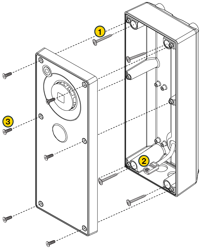
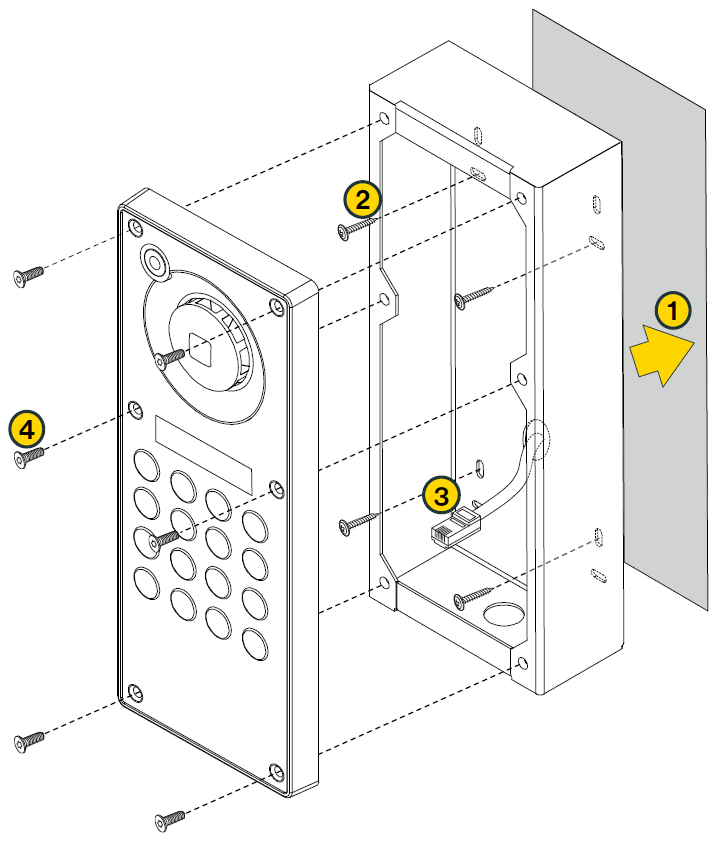
On-Wall Surface Mounting Procedure
- 1. Mount the TA-33 Backbox onto the wall using A4 socket head screws
- 2. Plug the Ethernet cable into RJ-45 port on the station. Or connect a 24VDC PSU
- 3. Mount the Turbine station onto the back box with the M5 fasteners provided. Apply 1.5 Nm torque
Ensure the station is mounted vertically with the microphone aperture facing down
Ensure there is enough clearance under the station so that the microphone aperture is not smothered

|
To ensure the IP-66 rating, use the grommets and M20 cable gland provided for the cable holes on the back box. |
Flush Mounting
Flush Mount Backbox - TA-34
Flush Mounting Procedure
- 1. Insert the TA-33 Backbox into designated slot in the wall
- 2. Fasten the back box to the wall
- 3. Plug the Ethernet cable into RJ-45 port on the station. Or connect a 24VDC PSU
- 4. Mount the Turbine Extended Station onto the Backbox with the M5 fasteners provided. Apply 1.5 Nm torque
Ensure the station is mounted vertically with the microphone aperture facing down
Ensure there is enough clearance under the station so that the microphone aperture is not smothered


