Difference between revisions of "Monitoring redundancy in VS Operator"
From Zenitel Wiki
(Created page with "==Monitoring redundancy in VS Operator== The VS Operator can be used together with a redundant system, communicating with the Operational IP address. VS-Operator can provi...") |
|||
| (16 intermediate revisions by 2 users not shown) | |||
| Line 1: | Line 1: | ||
| − | + | {{AI}} | |
| − | The VS Operator can be used together with a redundant system, communicating with the Operational IP address. | + | The VS Operator can be used together with a [[Redundant Servers - ICX-AlphaCom|redundant system]], communicating with the Operational IP address. It can provide graphical indications of Server Status and Server Operational Mode, and also display the Power Supply status. |
| − | + | ==Monitoring Servers== | |
| − | |||
| − | |||
Here is a description on how to set up monitoring so the ICX-AlphaCom statuses can be viewed in VSOP. | Here is a description on how to set up monitoring so the ICX-AlphaCom statuses can be viewed in VSOP. | ||
| Line 11: | Line 9: | ||
<br style="clear:both;" /> | <br style="clear:both;" /> | ||
| − | + | ===AlphaPro Events=== | |
To pass the Server Status and Operational Mode to VS-Operator, we use a Dummy Number (9600) and the Custom Parameter feature. We also add an event to trigger a refresh of the status' towards VSOP using another dummy number (991) | To pass the Server Status and Operational Mode to VS-Operator, we use a Dummy Number (9600) and the Custom Parameter feature. We also add an event to trigger a refresh of the status' towards VSOP using another dummy number (991) | ||
| Line 18: | Line 16: | ||
<br style="clear:both;" /> | <br style="clear:both;" /> | ||
| − | + | {{Code2| | |
| − | IF %op(%udd(101),=,1) | + | IF %op(%udd(101),<nowiki>=</nowiki>,1) |
@*D1 M7F01 L(1)9600 U0 W1 W2 W0 W0 W0 | @*D1 M7F01 L(1)9600 U0 W1 W2 W0 W0 W0 | ||
ENDIF | ENDIF | ||
| − | IF %op(%udd(101),=,2) | + | IF %op(%udd(101),<nowiki>=</nowiki>,2) |
@*D1 M7F01 L(1)9600 U0 W2 W1 W0 W0 W0 | @*D1 M7F01 L(1)9600 U0 W2 W1 W0 W0 W0 | ||
ENDIF | ENDIF | ||
| − | IF %op(%udd(101),=,3) | + | IF %op(%udd(101),<nowiki>=</nowiki>,3) |
@*D1 M7F01 L(1)9600 U0 W1 W3 W0 W0 W0 | @*D1 M7F01 L(1)9600 U0 W1 W3 W0 W0 W0 | ||
ENDIF | ENDIF | ||
| − | IF %op(%udd(101),=,4) | + | IF %op(%udd(101),<nowiki>=</nowiki>,4) |
@*D1 M7F01 L(1)9600 U0 W3 W1 W0 W0 W0 | @*D1 M7F01 L(1)9600 U0 W3 W1 W0 W0 W0 | ||
ENDIF | ENDIF | ||
| − | + | }} | |
[[File:IPHA Event1.png|thumb|left|500px|Timeout event]] | [[File:IPHA Event1.png|thumb|left|500px|Timeout event]] | ||
<br style="clear:both;" /> | <br style="clear:both;" /> | ||
| − | + | {{Code2| | |
$ST L%1.dir W200 L991 | $ST L%1.dir W200 L991 | ||
IF %chg(1,0) | IF %chg(1,0) | ||
| − | IF %op(%syse(230),==,0) | + | IF %op(%syse(230),<nowiki>==</nowiki>,0) |
IF %syse(232) | IF %syse(232) | ||
WUDD 101 1 | WUDD 101 1 | ||
| Line 53: | Line 51: | ||
ENDIF | ENDIF | ||
WUDD 101 4 | WUDD 101 4 | ||
| − | + | }} | |
| − | + | ||
| + | ===VS-Operator configuration=== | ||
Create two icon sets to display the status. One icon set will be for the Operational Status of the ICX-AlphaCom, and the other will be to indicate the VS-Operator connection to the Operational Server. | Create two icon sets to display the status. One icon set will be for the Operational Status of the ICX-AlphaCom, and the other will be to indicate the VS-Operator connection to the Operational Server. | ||
The icons used in this example are created in PowerPoint. | The icons used in this example are created in PowerPoint. | ||
| − | + | ====Operational Status Icons==== | |
[[File:IPHA example3.png|thumb|left|200px]] | [[File:IPHA example3.png|thumb|left|200px]] | ||
<br style="clear:both;" /> | <br style="clear:both;" /> | ||
| Line 81: | Line 80: | ||
<br style="clear:both;" /> | <br style="clear:both;" /> | ||
| − | + | ====System Operation Icons==== | |
[[File:IPHA example5.png|thumb|left|200px]] | [[File:IPHA example5.png|thumb|left|200px]] | ||
<br style="clear:both;" /> | <br style="clear:both;" /> | ||
| Line 93: | Line 92: | ||
<br style="clear:both;" /> | <br style="clear:both;" /> | ||
| − | + | ====VSOP Map==== | |
To display the Icons, we need to create a Map page with a background. In the example below, the Zenitel logo and the icons for the ICX Primary and ICX Secondary has been created as a static image in Powerpoint. | To display the Icons, we need to create a Map page with a background. In the example below, the Zenitel logo and the icons for the ICX Primary and ICX Secondary has been created as a static image in Powerpoint. | ||
| Line 100: | Line 99: | ||
<br style="clear:both;" /> | <br style="clear:both;" /> | ||
| − | + | ====VSOP Startup script==== | |
If VSOP is started after the IPHA monitor scripts have already run in the ICX-AlphaCom Event Handler, the status of the Operational Server or System status unknown, so a startup script is needed the force the Event Handler to resend the status. Here, we send a command to the ICX-AlphaCom to start a 10 second timer on our Dummy Number 991 | If VSOP is started after the IPHA monitor scripts have already run in the ICX-AlphaCom Event Handler, the status of the Operational Server or System status unknown, so a startup script is needed the force the Event Handler to resend the status. Here, we send a command to the ICX-AlphaCom to start a 10 second timer on our Dummy Number 991 | ||
Click on Menu and Global Settings. Enable the Startup script and click on the 3 dots to open the editor. Add the following line; | Click on Menu and Global Settings. Enable the Startup script and click on the 3 dots to open the editor. Add the following line; | ||
| − | App.STE ("$ST L101 W100 L991"); | + | {{Code2| |
| + | App.STE ("$ST L101 W100 L991"); | ||
| + | }} | ||
[[File:IPHA example9.png|thumb|left|500px|Adding a Startup Script]] | [[File:IPHA example9.png|thumb|left|500px|Adding a Startup Script]] | ||
<br style="clear:both;" /> | <br style="clear:both;" /> | ||
| − | + | ||
| + | ====VSOP Filter==== | ||
In order to catch the custom parameters sent from the Event Handler we need a filter, and this filter must be tied to our first Dummy Number 9600. | In order to catch the custom parameters sent from the Event Handler we need a filter, and this filter must be tied to our first Dummy Number 9600. | ||
Click on Filter Sets, followed by Add and Station. | Click on Filter Sets, followed by Add and Station. | ||
| − | [[File:IPHA example10.png|thumb|left|500px| | + | [[File:IPHA example10.png|thumb|left|500px|Adding a Filter Set]] |
<br style="clear:both;" /> | <br style="clear:both;" /> | ||
| Line 118: | Line 120: | ||
Give the Filter a name, here we are using IPHA_State. Select On Custom Params and enable the check boxes for Show, Log and Script. Enter a Message Text to be displayed in the Journal and enter the Script. | Give the Filter a name, here we are using IPHA_State. Select On Custom Params and enable the check boxes for Show, Log and Script. Enter a Message Text to be displayed in the Journal and enter the Script. | ||
| − | + | {{Code2| | |
| − | int n1 = App.Params.Get("cp1", 0); | + | int n1 <nowiki>=</nowiki> App.Params.Get("cp1", 0); |
| − | int n2 = App.Params.Get("cp2", 0); | + | int n2 <nowiki>=</nowiki> App.Params.Get("cp2", 0); |
App.SetGPDState("Primary", n1, true, true); | App.SetGPDState("Primary", n1, true, true); | ||
App.SetGPDState("Secondary", n2, true, true); | App.SetGPDState("Secondary", n2, true, true); | ||
| − | + | }} | |
Press the Test button, followed by the OK button. | Press the Test button, followed by the OK button. | ||
[[File:IPHA example11.png|thumb|left|500px|Adding the Filter Script for On Custom Params]] | [[File:IPHA example11.png|thumb|left|500px|Adding the Filter Script for On Custom Params]] | ||
<br style="clear:both;" /> | <br style="clear:both;" /> | ||
| − | + | ||
| + | ====Adding devices to VSOP==== | ||
[[File:Vsop add.jpg|left|thumb]] | [[File:Vsop add.jpg|left|thumb]] | ||
<br style="clear:both;" /> | <br style="clear:both;" /> | ||
| Line 146: | Line 149: | ||
Place the icons on the map by drag and drop. | Place the icons on the map by drag and drop. | ||
| − | + | ==Redundant Power supplies== | |
The Power Supplies can be monitored, and faults and warnings can be logged. | The Power Supplies can be monitored, and faults and warnings can be logged. | ||
| Line 157: | Line 160: | ||
| − | + | ===AlphaPro Event=== | |
In AlphaPro configure the two TKIS-2 kits which receive the inputs from the Redundancy module as ''9901 Primary'' and ''9902 Secondary''. Put them both in a UDP group (UDP2 is used in this example), and create this event: | In AlphaPro configure the two TKIS-2 kits which receive the inputs from the Redundancy module as ''9901 Primary'' and ''9902 Secondary''. Put them both in a UDP group (UDP2 is used in this example), and create this event: | ||
[[File:IPHA example14.png|thumb|left|500px|Redundant power supply monitoring event]] | [[File:IPHA example14.png|thumb|left|500px|Redundant power supply monitoring event]] | ||
<br style="clear:both;" /> | <br style="clear:both;" /> | ||
| − | + | {{Code2| | |
| − | + | @*d1 M7F03 L(1)9901 U0 W%chg(1,0) W%sev(1) W0 W0 W0 "PSU%1.nam\t %1.nam\t" | |
| − | + | IF %chg(1,0) | |
| − | + | IF %op(%sev(1),<nowiki>=</nowiki>,1) | |
| − | + | LOG "Power redundancy DOWN for %1.nam server" | |
| − | + | STOP | |
| − | + | ENDIF | |
| − | + | IF %op(%sev(1),<nowiki>=</nowiki>,2) | |
| − | + | LOG "Power redundancy WARNING for %1.nam server" | |
| − | + | STOP | |
| − | + | ENDIF | |
| − | + | ENDIF | |
| − | + | LOG "Power redundancy OK for %1.nam server" | |
| + | }} | ||
| − | + | ===VS Operator Configuration=== | |
| − | + | ====VSOP Icons==== | |
Create a icon set (the icons used in this example is created in PowerPoint): | Create a icon set (the icons used in this example is created in PowerPoint): | ||
The GPD Icons used for the Redundant Power Supply statuses: | The GPD Icons used for the Redundant Power Supply statuses: | ||
| Line 192: | Line 196: | ||
<br style="clear:both;" /> | <br style="clear:both;" /> | ||
| − | + | ====VSOP Filter==== | |
In order to catch the custom parameters sent from the Event Handler we need a filter, and this filter must be tied to the TKIS-2 Power monitoring stations. | In order to catch the custom parameters sent from the Event Handler we need a filter, and this filter must be tied to the TKIS-2 Power monitoring stations. | ||
| Line 204: | Line 208: | ||
[[File:Vsop power filter.png|alt=|left|thumb|711x711px|Creating custom filter set]] | [[File:Vsop power filter.png|alt=|left|thumb|711x711px|Creating custom filter set]] | ||
<br style="clear:both;" /> | <br style="clear:both;" /> | ||
| − | int RED_state = App.Params.Get("cp1", 0); | + | {{Code2| |
| − | int RED_type = App.Params.Get("cp2", 0); | + | int RED_state <nowiki>=</nowiki> App.Params.Get("cp1", 0); |
| − | if (RED_state==1) | + | int RED_type <nowiki>=</nowiki> App.Params.Get("cp2", 0); |
| + | if (RED_state<nowiki>==</nowiki>1) | ||
{ | { | ||
App.SetGPDState("%CSP1", RED_type, true, true); | App.SetGPDState("%CSP1", RED_type, true, true); | ||
| − | if (RED_type==1) | + | if (RED_type<nowiki>==</nowiki>1) |
App.Log("Redundancy power for %CSP2 server is reported down", true, true); | App.Log("Redundancy power for %CSP2 server is reported down", true, true); | ||
| − | else if (RED_type==2) | + | else if (RED_type<nowiki>==</nowiki>2) |
App.Log("Redundancy power for %CSP2 server reports a warning", true, true); | App.Log("Redundancy power for %CSP2 server reports a warning", true, true); | ||
} | } | ||
| − | if (RED_state==0) | + | if (RED_state<nowiki>==</nowiki>0) |
{ | { | ||
App.SetGPDState("%CSP1", 3, true, true); | App.SetGPDState("%CSP1", 3, true, true); | ||
App.Log("Redundancy power for %CSP2server is reported OK", true, true); | App.Log("Redundancy power for %CSP2server is reported OK", true, true); | ||
} | } | ||
| − | + | }} | |
{{obs|''%CSP1'' (custom string parameter 1) refers to the Source Name of the GPD.}} | {{obs|''%CSP1'' (custom string parameter 1) refers to the Source Name of the GPD.}} | ||
| Line 225: | Line 230: | ||
<br style="clear:both;" /> | <br style="clear:both;" /> | ||
| − | + | ====Adding devices to VSOP==== | |
Add two GPD devices. Name the 2 GPD devices 'PSUPrimary' and 'PSUSecondary'. Set the Source name field for Primary and Secondary respectively. Set the Icon Set for PSU Monitoring. | Add two GPD devices. Name the 2 GPD devices 'PSUPrimary' and 'PSUSecondary'. Set the Source name field for Primary and Secondary respectively. Set the Icon Set for PSU Monitoring. | ||
[[File:Vsop power gpd.png|alt=|left|thumb|500x500px|GPD name reference]] | [[File:Vsop power gpd.png|alt=|left|thumb|500x500px|GPD name reference]] | ||
| Line 233: | Line 238: | ||
<br style="clear:both;" /> | <br style="clear:both;" /> | ||
Place the GPS Icons on the Map. Optionally, create Icons for the Power Monitoring TKIS-2 units and place them on the Map. | Place the GPS Icons on the Map. Optionally, create Icons for the Power Monitoring TKIS-2 units and place them on the Map. | ||
| + | |||
| + | [[Category: Redundancy]] | ||
| + | [[Category: VS-Operator]] | ||
| + | [[Category: VS-Operator - Configuration examples]] | ||
Latest revision as of 14:55, 8 November 2023
The VS Operator can be used together with a redundant system, communicating with the Operational IP address. It can provide graphical indications of Server Status and Server Operational Mode, and also display the Power Supply status.
Monitoring Servers
Here is a description on how to set up monitoring so the ICX-AlphaCom statuses can be viewed in VSOP.
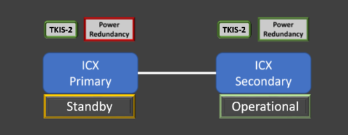
An example of the VS-Operator display:
AlphaPro Events
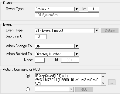
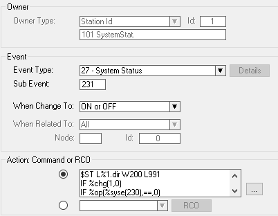
To pass the Server Status and Operational Mode to VS-Operator, we use a Dummy Number (9600) and the Custom Parameter feature. We also add an event to trigger a refresh of the status' towards VSOP using another dummy number (991)
In AlphaPro configure these two events:
Action commands:
IF %op(%udd(101),=,1)
@*D1 M7F01 L(1)9600 U0 W1 W2 W0 W0 W0
ENDIF
IF %op(%udd(101),=,2)
@*D1 M7F01 L(1)9600 U0 W2 W1 W0 W0 W0
ENDIF
IF %op(%udd(101),=,3)
@*D1 M7F01 L(1)9600 U0 W1 W3 W0 W0 W0
ENDIF
IF %op(%udd(101),=,4)
@*D1 M7F01 L(1)9600 U0 W3 W1 W0 W0 W0
ENDIF
Action commands:
$ST L%1.dir W200 L991
IF %chg(1,0)
IF %op(%syse(230),==,0)
IF %syse(232)
WUDD 101 1
STOP
ENDIF
WUDD 101 2
STOP
ENDIF
ENDIF
IF %syse(232)
WUDD 101 3
STOP
ENDIF
WUDD 101 4
VS-Operator configuration
Create two icon sets to display the status. One icon set will be for the Operational Status of the ICX-AlphaCom, and the other will be to indicate the VS-Operator connection to the Operational Server.
The icons used in this example are created in PowerPoint.
Operational Status Icons
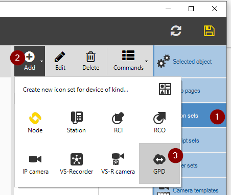
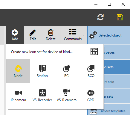
Navigate to the Icon sets menu and click Add, then choose GPD:
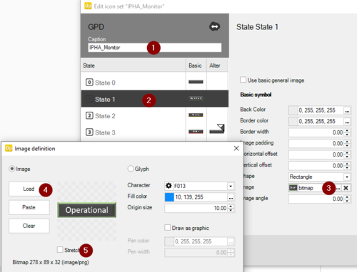
Give the GPD Icons a name, in this case IPHA_Monitor
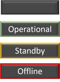
Add your four custom icons as GPD state 0-3 by clicking the 3 dots beside 'Image', selecting the Load button and navigating to your Icon. Note that after loading, you may need to disable the Stretch option to display correctly.
- State 0 - Blank Icon
- State 1 - Operational Icon
- State 2 - Standby Icon
- State 3 - Offline Icon
System Operation Icons
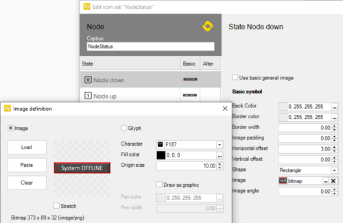
Navigate to the Icon sets menu and click Add, then choose Node:
Add your two custom icons as Node state 0-1 following the directions in the last step.
VSOP Map
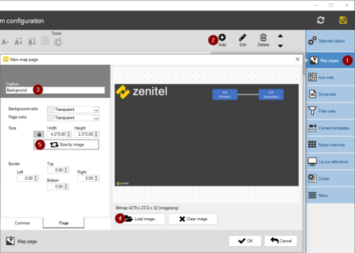
To display the Icons, we need to create a Map page with a background. In the example below, the Zenitel logo and the icons for the ICX Primary and ICX Secondary has been created as a static image in Powerpoint.
Click on Map Pages, followed by Add. Give the map a name and load in the background image. Resize accordingly.
VSOP Startup script
If VSOP is started after the IPHA monitor scripts have already run in the ICX-AlphaCom Event Handler, the status of the Operational Server or System status unknown, so a startup script is needed the force the Event Handler to resend the status. Here, we send a command to the ICX-AlphaCom to start a 10 second timer on our Dummy Number 991
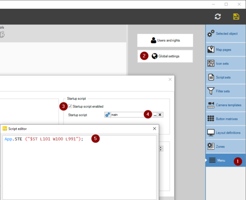
Click on Menu and Global Settings. Enable the Startup script and click on the 3 dots to open the editor. Add the following line;
Action commands:
App.STE ("$ST L101 W100 L991");
VSOP Filter
In order to catch the custom parameters sent from the Event Handler we need a filter, and this filter must be tied to our first Dummy Number 9600.
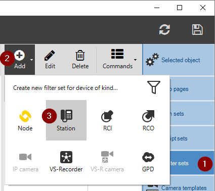
Click on Filter Sets, followed by Add and Station.
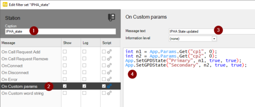
Create a custom filter using the On Custom Params message
Give the Filter a name, here we are using IPHA_State. Select On Custom Params and enable the check boxes for Show, Log and Script. Enter a Message Text to be displayed in the Journal and enter the Script. Action commands:
int n1 = App.Params.Get("cp1", 0);
int n2 = App.Params.Get("cp2", 0);
App.SetGPDState("Primary", n1, true, true);
App.SetGPDState("Secondary", n2, true, true);
Press the Test button, followed by the OK button.
Adding devices to VSOP
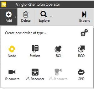
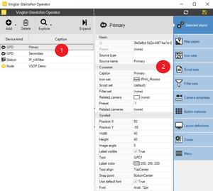
Add two GPD devices. Name these 2 devices Primary and Secondary. Set the Source name field for Primary and Secondary respectively. Set the Icon Set for IPHA_Monitor.
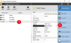
Add one Node Device. Name this the Node name of the system. Set the Icon Set for NodeStatus
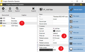
Add one Station device. Name this IP_HAFilter and set the AlphaCom Station to Node 1 Directory Number 9600 and the Filter Set to IPHA_state.
Place the icons on the map by drag and drop.
Redundant Power supplies
The Power Supplies can be monitored, and faults and warnings can be logged.
Here is a description on how to set up monitoring so the redundant power supply statuses can be viewed in VSOP.

|
The following description relates to the redundant power solution as mentioned further up in this article |
AlphaPro Event
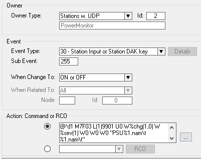
In AlphaPro configure the two TKIS-2 kits which receive the inputs from the Redundancy module as 9901 Primary and 9902 Secondary. Put them both in a UDP group (UDP2 is used in this example), and create this event:
Action commands:
@*d1 M7F03 L(1)9901 U0 W%chg(1,0) W%sev(1) W0 W0 W0 "PSU%1.nam\t %1.nam\t"
IF %chg(1,0)
IF %op(%sev(1),=,1)
LOG "Power redundancy DOWN for %1.nam server"
STOP
ENDIF
IF %op(%sev(1),=,2)
LOG "Power redundancy WARNING for %1.nam server"
STOP
ENDIF
ENDIF
LOG "Power redundancy OK for %1.nam server"
VS Operator Configuration
VSOP Icons
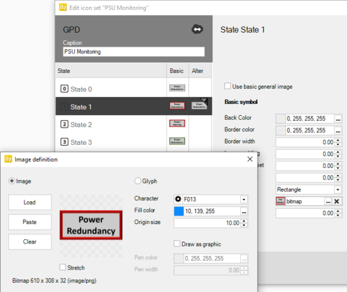
Create a icon set (the icons used in this example is created in PowerPoint): The GPD Icons used for the Redundant Power Supply statuses:
Navigate to the Icon sets menu and click Add, then choose GPD:
Name the Icon Set 'PSU Monitoring' and add your four custom icons as GPD state 0-3:
VSOP Filter
In order to catch the custom parameters sent from the Event Handler we need a filter, and this filter must be tied to the TKIS-2 Power monitoring stations.
Click on Filter Sets, followed by Add and Station.
Create a custom filter using the On Custom word string message
Give the Filter a name, here we are using PowerMonitor. Select On Custom word string and enable the check box for Script. As we are creating the Log messages from the script, we can leave the Show and Log checkboxes unchecked, and we do not need a message text. Copy and paste the script, press the Test button and then OK.
Action commands:
int RED_state = App.Params.Get("cp1", 0);
int RED_type = App.Params.Get("cp2", 0);
if (RED_state==1)
{
App.SetGPDState("%CSP1", RED_type, true, true);
if (RED_type==1)
App.Log("Redundancy power for %CSP2 server is reported down", true, true);
else if (RED_type==2)
App.Log("Redundancy power for %CSP2 server reports a warning", true, true);
}
if (RED_state==0)
{
App.SetGPDState("%CSP1", 3, true, true);
App.Log("Redundancy power for %CSP2server is reported OK", true, true);
}
Adding devices to VSOP
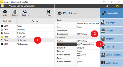
Add two GPD devices. Name the 2 GPD devices 'PSUPrimary' and 'PSUSecondary'. Set the Source name field for Primary and Secondary respectively. Set the Icon Set for PSU Monitoring.
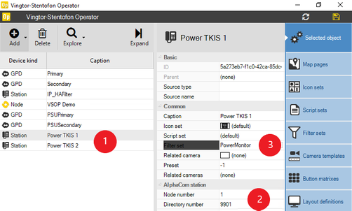
Add two Station devices, one for each TKIS (9901 & 9902). Name the TKIS-2 station 'Power TKIS 1' and 'Power TKIS 2' and select the station custom filter for Redundant Power Supply monitoring.
Place the GPS Icons on the Map. Optionally, create Icons for the Power Monitoring TKIS-2 units and place them on the Map.


