LenelS2 OnGuard - ICX-AlphaCom Integration: Difference between revisions
From Zenitel Wiki
| Line 127: | Line 127: | ||
$MPC 2 "0507 %1.dir(4,F) 6930 0000 0000 " | $MPC 2 "0507 %1.dir(4,F) 6930 0000 0000 " | ||
{{note| | {{note|Be aware of the '''<space>''' before the closing double quotation mark in the second line}} | ||
===Other Events and Actions=== | ===Other Events and Actions=== | ||
Revision as of 10:09, 3 June 2024
Introduction

|
This article relates to the integration between OnGuard and ICX-AlphaCom, or AlphaCom with software version 13.1.3.3 or newer. For older AlphaCom software, please refer to the article Lenel Onguard - AlphaCom (old versions) integration |
Article Scope
This article describes the interface of ICX-AlphaCom and AlphaCom XE platforms with OnGuard. OnGuard users will be able to configure ICX-AlphaCom and AlphaCom XE as a communication platform from within OnGuard System Administration.
ICX-AlphaCom and AlphaCom XE offer advanced communication and control capabilities. They provide the voice of security. This article includes descriptions of setup and configuration, operation, and any limitations and/or notes surrounding the solution. The setup and operation of ICX-AlphaCom and AlphaCom XE are very similar, as ICX-AlphaCom is built on the AlphaCom XE application software. Where this does not cause any confusion, the only reference will be made to the ICX-AlphaCom.
This article assumes that the reader is familiar with the setup of OnGuard and ICX-AlphaCom.
Prerequisites
Pre-Installation Checklist
- Use AlphaPro, the standard ICX programming tool to enter the parameters to enable communication between ICX and OnGuard.
- ICX software has been upgraded to version 1.0.3.1 or higher
- AlphaCom software has been upgraded to version 13.1.3.3 or higher
- OnGuard software is an actively supported version
- Zenitel intercom stations have been configured and point to the ICX
- Programming of the exchange (if necessary)
- OnGuard server configured on a compatible Operating System
Licensing
- Maximum Number of Intercom Exchanges (SWG-1340) – Contact VAR or LenelS2
- ICX: 1002602400 - ILI-IF
Installation and Configuration
Install Accessory Add-On
- Install x.x Zenitel ICX Accessory Add-On.msi, where x.x refers to the OnGuard software version
Note that when upgrading to a newer version of OnGuard, the Accessory Add-On installation needs to be performed again. All database information will still be present.
ICX System Configuration
Use AlphaPro, the standard ICX programming tool to enter the parameters to enable communication between ICX and OnGuard.
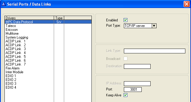
- Go to Exchange & System > Serial Ports and set the following parameters:
- MPC Data Protocol
- TCP/IP server
- Enter a Port number
- In the screenshot, port 3001 is used as an example, and is also the default port configured in OnGuard
Use a web browser to log into the ICX webserver, (default username/password = admin/alphaadmin)
- Select System Configuration > Filters
If the port is not in the list yet, use Add Filter to define it. In the above screenshot, it has been defined with the name 3001 but any meaningful name can be given. Enable this TCP port on the relevant Ethernet port (Eth0 or Eth1).
Ringing Group
In order to have the full benefit of the integration between ICX and OnGuard, operator stations should be placed in a ringing group. This should be done even if there is only a single operator station.
There are 10 predefined ringing groups, with group numbers 51-60 and default directory numbers 6701-6710. If required, more ringing groups can be added as ICX handles up to 250 groups.
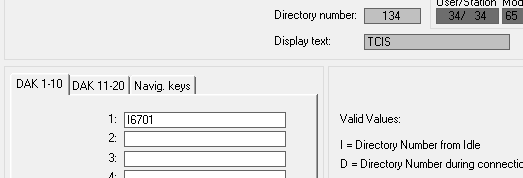
Remote stations calling these operators must call 6701. Substations with only a single call button (Direct Access Key – DAK) must have DAK-1 programmed as I6701.
Call Request Information
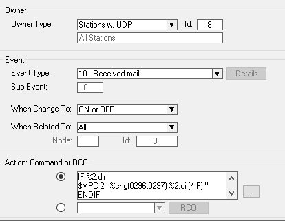
ICX must sent call request information to OnGuard. This is done by programming the ICX event handler:
The action string for the above event is:
IF %2.dir
$MPC 2 "%chg(0296,0297) %2.dir(4,F) "
ENDIF
Faulty Line
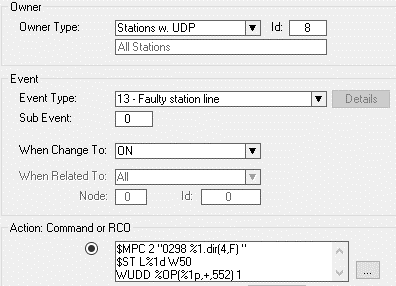
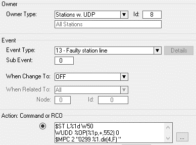
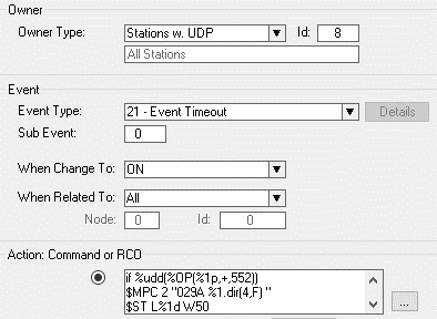
ICX must sent faulty line information to OnGuard. This is done by programming the ICX event handler with 3 events:
The action string for the above event is:
$MPC 2 "0298 %1.dir(4,F) "
$ST L%1d W50
WUDD %OP(%1p,+,552) 1
The action string for the above event is:
$ST L%1d W50
WUDD %OP(%1p,+,552) 0
$MPC 2 "0299 %1.dir(4,F) "
The action string for the above event is:
if %udd(%OP(%1p,+,552))
$MPC 2 "029A %1.dir(4,F) "
$ST L%1d W50
stop
endif
$MPC 2 "029B %1.dir(4,F) "
$ST L%1d W50
Door Opening from an Operator Station
Very often, an operator will want to open a door by simply pressing a digit on the station keypad during a conversation with a person near that door. For ICX, this can be done by pressing digit 6. Normally this will operate a relay directly but, in this case, OnGuard needs to be notified, after which OnGuard can take the action to open the door.
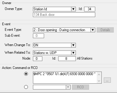
The event below is an example of how this can be done.
The door intercom has directory number 134 and there is a conversation with an operator. When digit 6 is pressed, the event sends the directory number and code 6930 to OnGuard. Within OnGuard, 6930 must be defined as an Intercom function. Using Global I/O it is then possible to define the door that needs to be opened when this code is received.
$MPC 2 "0507 %1.dir(4,F) 6930 0000 0000 "
Other Events and Actions
Using the ICX event handler and the Global I/O + Linkage Server functionality of OnGuard, it is possible to solve many customer requirements.
ITSV as an Operator Station
The ITSV is a Vingtor-Stentofon SIP telephone. To be able to use it as an operator intercom, the following setting must be made:
- Log in into the ITSV web page (default credentials: admin/alphaadmin)
- Navigate to Call Settings related to the account that is used to connect to the ICX.
To reduce the time that it will take to detect and display a connection error it is necessary to reduce the registration time-out:
- Navigate to Account/Account 1/SIP Settings and make the following settings:
- Register Expiration (m): 1
- Click Save
- At the top of the page, click Apply
OnGuard Configuration
The following steps are done in OnGuard System Administration.
Define System
- Select menu item Additional Hardware > Intercom Devices
- Select the tab Intercom Devices and click the Add button
- Select the LAN option
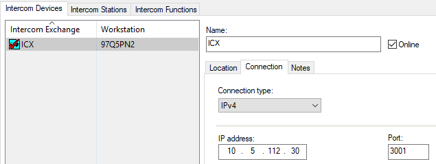
- Enter the IP address of the ICX and the port number as used in the steps above (port 3001 in this example)
- Click OK
Devices
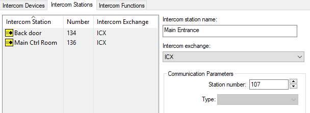
- Select the tab Intercom Stations and click Add
- Enter a name and a directory number for each station which is in the system
- OnGuard uses integer values for the directory numbers, and it is not possible to have directory numbers with a leading 0
- Only use directory numbers with a maximum of 4 digits
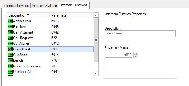
Add Intercom Functions
- In OnGuard System Administration, navigate to Additional Hardware > Intercom Devices > Intercom Functions
Add all intercom functions that are expected to be used, with the appropriate directory number.
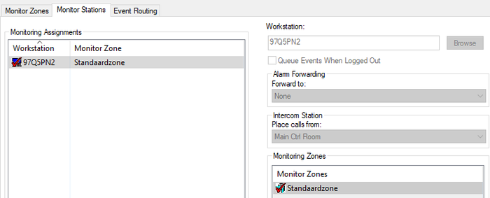
Monitor Station Setup
- In OnGuard System Administration navigate to Monitoring > Monitor Zones …
- Select the tab Monitor Stations
- Click Add
Configure Monitor Stations:
- Workstation: The client with which an operator intercom station shall be associated
- Monitor Zone: Default zone or zone chosen to contain Intercom equipment
- Forward to: Another workstation that will receive intercom alarms (optional)
- Place calls from: Intercom Station that will be used as the main station for this workstation
When a monitoring station has been configured for a workstation, it will be the default station for that workstation. The Call Intercom function from OnGuard’s Alarm Monitoring System Tree icon, map icon or alarm list entry will use the monitoring station as its source.
Alarm Monitoring
Configuration
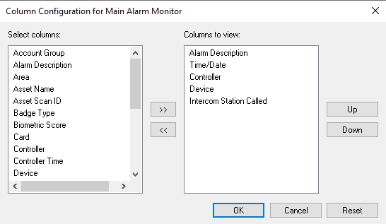
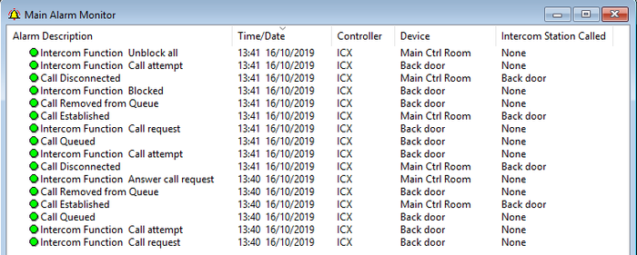
In order to show the directory numbers of both stations in a conversation, make sure that the column Intercom Station Called is shown. To make this column visible:
- Select the Main Alarm Monitor window and choose menu item Configure > Columns...
- Select Intercom Station Called to show under Columns to view
System Tree
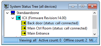
- In OnGuard Alarm Monitoring navigate to View > System Status > 1 System Status Tree
The System Status Tree window lists every system device defined in OnGuard System Administration.
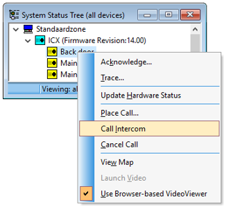
During normal operation, all intercom devices configured in OnGuard System Administration should appear in the Alarm Monitoring System status tree as online (no red or yellow x). Users will have the ability to execute the following commands (intercom right-click options):
- Place Call: Displays a dialog box where you can enter the station number you are calling to.
- Cancel Call: Cancels the intercom call.
- Call Intercom: Places a call using the intercom station configured in System Administration > Monitoring > Monitor Zones, and then selecting the Monitor Stations tab.
Main Alarm Monitor
In the Main Alarm Monitor screen, the following messages are displayed related to intercom station status changes:
- Call Queued: Queuing station
- Call Established: Originating station and called station
- Call Disconnected: Originating station and called station
- Call to a Private Subscriber: Originating station and called station
- Call to a Busy Subscriber: Originating station and called station
- Intercom Function with the defined intercom function
In general, it is possible for OnGuard to trigger any feature that AlphaCom supports (over 100 features are available as standard), while AlphaCom can send information to OnGuard on any event inside the AlphaCom. These are known as intercom functions. Through the use of the Intercom Function, it is possible to define a specific message for every function in the AlphaCom.
OnGuard Maps
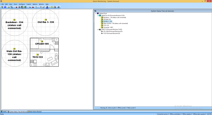
All intercom devices that exist in OnGuard Alarm Monitoring can effectively be placed on a map where they can be monitored.

|
For more information on associating devices with maps, refer to the MapDesigner User Guide from LenelS2. |
Icons in maps have the following appearances depending on intercom station statuses:
- Idle
- Connected: Station is in a conversation with another station
- InQueue: Station has initiated a call request and is in a call queue
- Blocked: Station is temporarily blocked by a guard from making calls
- AnalyticsEvent: An audio analytics event (glass breakage, car alarm, aggression, gunshot) has been detected
- LineError: A line error to the station has been detected
- Offline: The station is offline. This state is shown when there is no data communication at all between OnGuard and AlphaCom, and all station icons will show the Offline state.
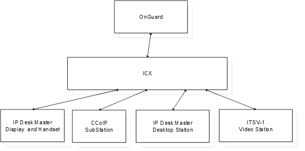
System/Integration Topology
Topology
Limitations
- Note: If an unsupported message is received from the intercom station, Communications Lost will be seen within OnGuard for approximately 10 – 30 seconds. Communication between OnGuard and intercom will be lost during this time. In the OnGuard Alarm Monitoring system tree, the status of the station at the time when communication was lost will be displayed and remain so next to the intercom station until Alarm Monitoring is restarted.
- For example, during a call from intercom master station # 136 to Substation #134, when a function number (example: 6) that was not configured is entered, the intercom system will display as offline in Alarm Monitoring.
- When this situation occurs where Communications Lost is displayed in Alarm Monitoring, it is an indication that the ICX is misconfigured and should be reconfigured.
- In OnGuard Alarm Monitoring, AlphaCom displays firmware version 13.01 when AlphaCom firmware version is 13.1.3.3.
- In OnGuard Alarm Monitoring, ICX displays firmware version 14.00 when ICX package software is version 1.0.3.1; this is because the underlying application software is version 14.01
- OnGuard defines intercom directory numbers as integers; the supported range in the OnGuard-AlphaCom integration is 1-9999. Directory numbers with a leading ‘0’ should not be used inside AlphaCom.


