Difference between revisions of "ISO Data Link Layer"
From Zenitel Wiki
(→Parsing of commands) |
(→Formatting Specifers) |
||
| Line 291: | Line 291: | ||
It’s not necessary to fill in all bytes in the headers. Reserved characters are used to set the position in the message where the following bytes will be filled in (the omitted fields have default values, see below). | It’s not necessary to fill in all bytes in the headers. Reserved characters are used to set the position in the message where the following bytes will be filled in (the omitted fields have default values, see below). | ||
| + | |||
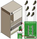
| + | [[Image:Station and RCO connection to ASLT in E20 and E26.jpg|left|150px|thumb|Station and RCO connection to ASLT in AlphaCom E20 and E26]] | ||
Revision as of 10:10, 27 June 2007
The protocol is based on the ISO 1745 standard using the ISO 1155 longitudinal parity. The protocol can be used with RS232 and RS422 pointtopoint connection, but also with RS485 multidrop bus connection.
The ISO Data Link layer procedure is based on the ISO1745 standard: Information processing Basic mode control procedures for data communication systems. The standard includes the concept of having a Control Device, Master Device and Slave Device.
The Control Device polls the devices, one at a time in an orderly fashion, inviting them to transmit messages. The devices that transmits a message becomes the Master Device. This device selects the destination device, which becomes the Slave Device, inviting it to receive an information message. The Master Device sends the message and the Slave Device acknowledges the message.
The AlphaCom module is always the Control Device.
Contents
- 1 Overview
- 2 Transmission Control Characters used
- 3 Device Id
- 4 Polling
- 5 Selecting
- 6 Messages
- 7 Recovery Procedures (Timers)
- 8 Stentofon Data Link Layer
- 9 Stentofon Simple Link Layer
Overview
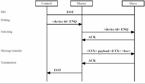
A complete message transmission sequence progress as follows:
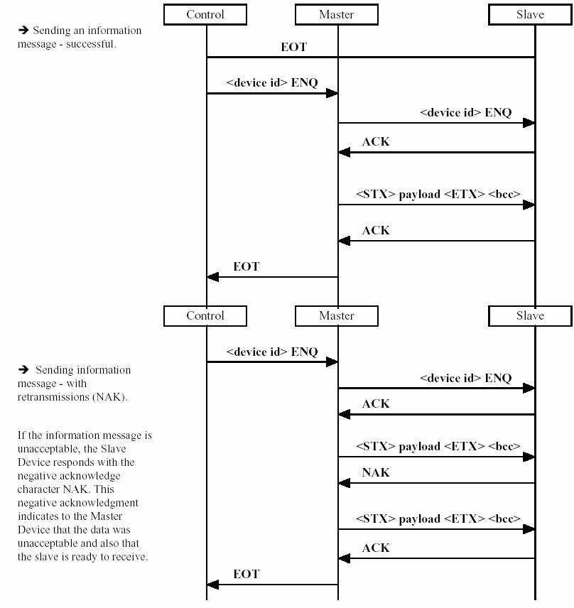
<br\> <br\> <br\> <br\><br\><br\><br\><br\><br\><br\><br\><br\><br\><br\><br\><br\><br\>
Transmission Control Characters used
The following control characters are used in the protocol:
The first 32 characters, ASCII 0 31 (0x00 0x1F) is not allowed in the payload of an message.
Note that the message’s Block Check Character can have any value, including the reserved transmission control characters!
STX - Start of text
STX is a transmission control character which precedes a text and which is used to terminate a heading. STX is transmitted by the Master Device.
ETX - End of text
ETX is a transmission control character which terminates a text. ETX is only transmitted by the Master Device and calls for a reply from the Slave Device. ETX is followed by a BCC, “block check character”.
EOT - End of Transmission
EOT is a transmission control character used to indicate the conclusion of the transmission of one text. EOT may be transmitted by a Control, Master or Slave Device. The Control Device transmits EOT to anticipate the reception of a forward supervisory sequence. The Master Device in the system transmits EOT to relinquish its right to transmit in favor of the Control Device.
ENQ - Enquiry
ENQ is a transmission control character used as a request for a response from a remote device. ENQ is transmitted by the Control Device during polling and by the Master Device during selecting.
ACK - Acknowledge
ACK is the transmission character transmitted by a receiver as an affirmative response to the sender.
NAK - Negative acknowledge
NAK is a transmission control character transmitted by a receiver as a negative response to the sender <br\><br\><br\>
Device Id
The Device Id is an UINT1 value which is uinique within an exchange.
Selecting a device in another exchange (Routing)
If the Master Device has a message to a device in another exchange, the Router is selected. The Router has device id 204 (0xCC) and answers the enquiry, and receives the message, on behalf of the destination device. This means that each device has to know which AlphaCom module they belong to.
The Master Device has completed its transmission upon receipt of ACK from the Router. Acknowledgment / handshake between devices on different modules must be handled at the application layer.
Broadcast
The Master Device uses a broadcast id when selecting for a broadcast message. It is the responsibility of the Master Device to ACK the selecting supervisory by transmitting the positive acknowledge character ACK. <br\><br\><br\>
Polling
Polling is the process of inviting devices, one at a time in an orderly fashion, to transmit messages. The basic function of polling is to prevent contention by ensuring that only one device transmits at a time. The polling process can only be performed by a Control Device, following EOT.
When a device receives its appropriate polling supervisory sequence, it becomes the Master Device.
The format of the polling supervisory sequence is:
<br\><Device Id> ENQ
Polling sequences are always preceded by EOT. <br\><br\><br\>
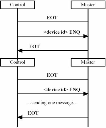
--> Polling sequence where a device is invited to send a message. The device becomes the Master Device when it receive its appropriate polling supervisory. In this example the device has no messages and sends the termination supervisory sequence EOT.<br\><br\><br\><br\><br\><br\>
--> Polling sequence when the Master Device has a message to send. The Master Device is allowed to send only one message pr. polling sequence. This means if a device has several messages to send it must wait until the next time it receives it’s appropriate polling supervisory. <br\><br\><br\><br\><br\><br\><br\><br\><br\>
Selecting
Selecting is the normal process for inviting one device to receive an information message. The selecting process can only be performed by a Master Device. The selecting supervisory sequence uniquely identifies the device by means of its Device Id.
The device selection supervisory sequence calls for a status reply from the selected device. If no response, or invalid response is received, the Master Device must take action to recover the communication.
Messages
The information messages have the following format: <STX> <encoding type> <data……….> <ETX> <bcc> The sequence which constitutes the message is prefixed by the start of text (STX) character and is terminated only with the end of text (ETX) character.
- <encoding type> is a UINT1 value identifying the coding of the message.
- 72 (0x48) (‘H’) = Standard AlphaCom Data Protocol message
- This format means that the rest of the message (data) is normally encoded as two Hexadecimal characters pr byte. The exception to this is if an 34 (0x22 = ASCII Double Quote) value is encountered. This means that the remaining part of the is not encoded. This makes it possible to have uncoded ASCII text in the messages.
- Normally it’s the link layers responsibility to encode/decode messages.
- is a network layer message data as delivered to the link layer, which is encoded according to <encoding type>.
- <bcc> is the Block Check Character as specified in ISO1155. This is the bytewise exclusiveor of all bytes, including the <STX> and <ETX> character.
Replies
If the information message was acceptable the Slave Device replies by transmitting the acknowledge character ACK. As for now the Master Device is allowed to send only one information message after becoming the Master Device. The Master Device therefore passes to the termination phase (sending EOT).
Broadcast Message
It is the responsibility of the Master Device to acknowledge the message by sending the positive acknowledge character ACK.
Termination
- When a device refuses the establishment of a data link, either because it has nothing to send (negative reply to polling), or because its unable to transmit (negative reply to polling), or because it is unable to receive (negative reply to selecting)
- When the Master Device has successfully transmitted data. The Master Device then transmits the end of transmission character EOT, indicating to the Slave Device that the Master Device has no more data to send. The Master Device thus relinquishes its right to transmit (unless it is also the Control Device).
- When an unusual situation arises where the master desires to stop the transmission in progress. If a Master Device sends EOT at any time other than after a terminated transmission, the transmission in progress is said to be aborted. A slave never sends EOT. In all circumstances the sending of EOT by any of the devices terminates the transmission, this means returning the responsibility and the control of the communication to the Control Device. This function is called ``Return to control’’.
Recovery Procedures (Timers)
A number of recovery procedures are required to deal with various abnormal situations. After appropriate time-out periods it shall be the responsibility of either the Control Device or the Master Device (never of a Slave Device) to take action.
- The Master Timer is set to 1 second and controls how long a Master Device may be active. The timer is only used by the Control Device. The main purpose of this timer is to take care of the situation where the Master Device “dies” before returning control to the Control Device. The Control Device transmits an EOT if the Master Timer times out. This is done when the link is idle (no traffic) to regain control.
- The ACK Timer is set to 100ms and specifies the time waiting for an ACK after sending an polling supervisory, inquiry supervisory or information message. Maximum 1 retransmission.
An information message is discarded if the Master Device, for some reason, is unable to send a message.
Stentofon Data Link Layer
The Stentofon Data Link Layer protocol uses a ``Sliding Window’’ technique with ``Go Back N’’ flow control. The protocol is very similar to the protocol used in the Inter Card Cage communication (ICCL) internal to the AlphaCom exchange. As the Stentofon Data Link Layer protocol is used in a pointtopoint full duplex communication, address information is unnecessary. The address field in the header of the ICCL protocol is here used to define coding format of the Network Layer data frame. The total length of the Stentofon Link Layer frame is limited to maximum 128 characters.
Transmission Control Characters
- <Stop Flag> 0xF1
- <Escape Flag> 0xF0
The only transmission control character is the STOP_FLAG used as terminating character of all Link Layer frames. When a STOP_FLAG is received, it indicates that a complete frame has been received. When a STOP_FLAG is sent, the link is free, and more frames may be sent. The STOP_FLAG byte value has to be unique within the frame.
Any other character with value 0xF1 must be replaced with an escape sequence consisting of two characters. If the STOP_FLAG is represented in the header, user information field (payload) or check sum field, the STOP_FLAG is replaced by an ESCAPE_FLAG followed by 0x00. If the ESCAPE_FLAG byte pattern is part of the header, payload or checksum field, it is replaced by ESCAPE_FLAG followed by 0x01.
The two byte values, if occurring in a frame, are thus transmitted in the following way:
- 0xF1 > 0xF0 0x00 (11110001 > 11110000 00000000)
- 0xF0 > 0xF0 0x01 (11110000 > 11110000 00000001)
Frame Structure
The general structure of the Stentofon Link Layer frame is:
<Header> <Data…..> <BCC> <STOP_FLAG>
Detailed field description:
<Header> is one 8-bit byte sub-divided into: <Unused> <Encoding type> <Sequence number> <Frame type>
- <Unused> 2 bit
- <Encoding type> 1 bit, encoding type for the payload data field: <br\>
- 0 = binary coded format <br\>
- 1 = hexadecimal coded (ASCII) format
- <Sequence number> 3 bits, giving a sequence number 1 ... 7, starting at 1, counting up to 7, and then starting at 1 again. Used to <br\>
- ensure correct sequence of messages.
- <Frame type > 2 bits, defining 4 possible frame types:
- 0 (00) = Reserved ICC protocol (Multi-module)
- 1 (01) = Information/Message/Idle frame
- 2 (10) = ACK frame
- 3 (11) = NAK frame
<Data….> consists of a network layer frame of maximum 125 byte encoded according to <encoding type>, or may be empty. Data is often referred to as payload.
<BCC> Block Check Character, represented as the longitudinal parity of the frame preceding the BCC
<STOP_FLAG> 0xF1, described above.
Frame Description
Encoding type 0 means that the field is binary data.
- - Data needs no reformatting.
Encoding type 1 means that the field contains hexadecimal data.
- - Data is represented by ASCII characters `0’ ... `9’ and `A’ ... `F’.
- - Each byte of original binary data is converted to 2 ASCII characters. The data are converted back to binary form before they are sent to the Network Layer.
- - If the character ` ‘’ ‘ (double quote, 0x22) is received within a hexadecimal message, the rest of the message is uncoded (ASCII text). The ` ‘’ ‘ is stripped off, and its position is handed over to the Network Layer, so that if the message is to be retransmitted, the double quote is reinserted and the ASCII text part will not be coded to hexadecimal.
- - When a hexadecimal encoding type is used, a CR (carriage return) character is added at the end of the field to increase readability. This character is also stripped off before the data is sent to the Network Layer.
Information/Message Frame
The Information/Message Frame type (type 1) typically will have a Network Layer Frame as payload.
Idle Frame
A special version of the message frame is the Idle Frame, defined by a field containing a Network Layer Frame with only the address header (no payload message code and parameters).
When no data are ready for transmission for a given time, idle frames are transmitted at regular intervals to check the quality of the data channel, and also to detect interruption of the channel (watchdog function). Idle frames are also used for resynchronization of sequence numbers. Idle frames are acknowledged in the same way as data messages. The format of the idle frame is as follows, where the size of each field is 1 byte:
- = <source node><source device><destinatin node><destination device>
<br\><br\>
Acknowledge Frame
The ACK frame (type 2) is used to acknowledge frames that are correctly received. The sequence number is derived from the frame it acknowledges.
Negative Acknowledge Frame
The NAK frame (type 3) is used to request for retransmission of a given message.
ACK and NAK frames will have priority for sending before any other messages.
Link Control, Supervision and Error Recovery Procedures
As the protocol may be used on intercontinental links with long delays (up to 500 600 ms roundtrip delay on a satellite |hop), special precautions must be taken to secure transmission quality without introducing too long delay in the forward path when conditions are good. Therefore, a sliding window mechanism is used to maintain correct sequencing of messages in case of transmission errors.
Sliding Window Protocol
A sliding window protocol with sending window size 7 is used. This means that 7 messages may be sent on the link before a response is required for any of them. At the receiving end, window size 1 is used, i.e. if a message is lost, the lost message plus all messages after the lost one must be retransmitted.
At the transmitting end, the Message Frames are numbered with a sequence number and inserted into a window buffer when sent, and removed when acknowledged. Before a new frame is sent, the previous frame must be completed (STOP_FLAG sent). When the buffer is full, transmission of new frames has to wait until an acknowledge is received. The Acknowledge Frame carries the same sequence number as the frame it acknowledges. If an acknowledge is received for a frame that is not the oldest one in the window buffer, it means that an Acknowledge Frame is lost or skipped at the receiving end, and the acknowledged frame and any older frames are removed from the buffer. If a NAK frame is received, the corresponding frame plus the newer frames (if any) are retransmitted, and the older frames are removed from the buffer.
At the receiving end, incoming frames are checked for errors, and if OK, an ACK frame with the same sequence number is transmitted back to the sender. The frame is then decoded to binary form (if necessary) and sent to the Network Router. If an error is detected, either in the current frame or if there is a frame sequence number missing, NAK frame is sent back to the sender with the sequence number of the frame with error or missing. The receiver then discards all received frames until the one with the correct sequence number is received, and normal operation is resumed. Since an Idle Frame is only transmitted when the window buffer is empty, it is used to synchronize sequence numbering at the other end of the link. After a reset, the transmission always starts with at least one Idle Frame.
Link Supervision
If there is no response from the other end of a link within a given time (calculated from the normal delay of the link) after the last frame is sent, the contents of the window buffer is retransmitted. If no response is obtained after 2 attempts, the window buffer is cleared, transmitter reset, and Idle frames transmitted with specific intervals. If contact with the other end is reestablished, an OKmessage is sent to the Network Router so that data communication can be resumed.
Simple implementation
An external computer can run with a sliding window size of one, i.e. for each message you send you must wait for the acknowledge from the AlphaCom. Sending/receiving NAKs can also be skipped as both ends always must have (fast) timeouts to handle errors.
Stentofon Simple Link Layer
This point-to-point link layer can be used for inter-node links, links to local devices and as an operator interface. (Multiple devices can be connected to a single link using a SCE board or something similar).
To get response messages back to the port, you must define at least one external device on this port. If several devices are set up on the port, the lowest device number will be used as default device number in commands where device number is not stated explicitly.
There are no link addresses, polling, time-outs, acknowledgments, re-transmissions or any explicit multipoint support.
Link Layer Output Message Format
Outgoing AlphaNet network layer messages are formatted like this:
HHHHHH...HH=SS<CR><LF>
<HH> represents a binary byte as 2 hexadecimal digits.
Long text parameters are usually located at the end of a data message. In this case the exchange will send the text as readable ASCII within quotes.
HHHHHH...HH”tttt”=SS<CR><LF>
“ and = are syntax delimiters in the format. <br\> <SS> is the 8-bit checksum of the original binary network layer message represented as 2 hex digits. The checksum is an ISO-1155 (bytewise XOR) checksum.
If the trailing text parameter(s) contains any “ or control characters, the leading bytes of the text will be hex-coded instead up to and including the last “ or control character (as if the trailing text parameter(s) started there instead). What is considered trailing text parameter(s) is the same as for the ISO-1745-based link layers (Using the internal “Encoding Hint”).
Link Layer Input Message Syntax
The Input Message Syntax is a superset of the Output Message Format.
HHHHHH...HH=SS<CR>
The basic format is a hex coded network layer message, including check sum. This format is excellent when produced by a computer controlling the exchange. Example (dial digits): 010101410141123400503201107F20102F<CR>
- Incoming messages are terminated by <CR>. The optional <LF> and any other control characters or spaces after <CR> before the next message are discarded.
- The incoming messages (without the terminating <CR> and other inter-message characters) are converted by the same preprocessor as is used for AlphaNet messages from Command Strings before they are routed towards their destination. If the converter finds syntax, length or checksum errors, the message is discarded silently. Messages without checksum are always accepted as long as they do not have any other errors.
Parsing of commands
Many additions and simplifications are allowed to facilitate Operator (and Event Handler Action String) use.
$DD L101 G102<CR>
$DIAL_DIGITS L101 G102<CR>
- The parsing is “stateless”, so Hex bytes and formatting specifiers do NOT change meaning depending on sequence.
- Uppercase/Lowercase is not significant, except inside strings (I.e. inside “”, ‘’ or ``).
- Whitespace is defined as a sequence of one or more of these characters:<br\>
‘ ‘ (space), ‘,’ (comma), <TAB>, <LF>, <FF>, <BS> and <BEL>. <br\> Whitespace is allowed and ignored everywhere, except in the middle of hex-bytes, decimal numbers, directory numbers, strings, message type names, etc.<br\> Whitespace is however often necessary when used to delimit the parameter (list) of a formatting specifier from whatever follows after. If the (last) parameter is a (decimal/directory) number, whitespace must be used if a hex-coded byte follows. Whitespace is also needed after message type names/acronyms if the following is a letter, digit or underscore (‘_’). (See below for more on formatting specifiers).
Formatting Specifers
All formatting specifiers are a single (non-hex-digit, non-whitespace) graphic “key” character plus sometimes parameters (or text delimited by same key character).
Positioning
It’s not necessary to fill in all bytes in the headers. Reserved characters are used to set the position in the message where the following bytes will be filled in (the omitted fields have default values, see below).


