IP Substation Board Connection: Difference between revisions
From Zenitel Wiki
No edit summary |
No edit summary |
||
| Line 5: | Line 5: | ||
{| | {| | ||
|- | |- | ||
|width="100pt"|'''P1''': | |width="100pt" valign="top" |'''P1''': | ||
|width="300pt"|RJ45 connector for LAN connection<br> | |width="300pt"|RJ45 connector for LAN connection<br> | ||
The station can be powered from this connection if the line supports Power over Ethernet. | The station can be powered from this connection if the line supports Power over Ethernet. | ||
Revision as of 20:46, 10 October 2007
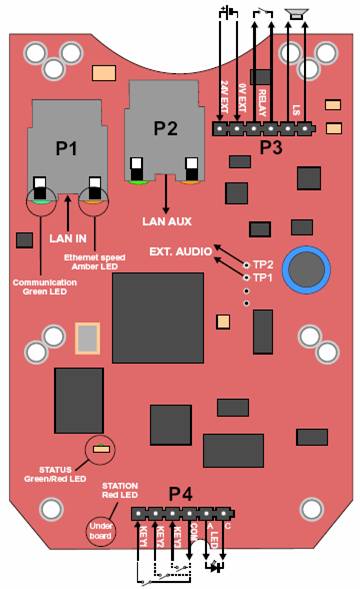
There are four connectors on the IP substation board, P1-P4.
| P1: | RJ45 connector for LAN connection The station can be powered from this connection if the line supports Power over Ethernet. |
| Event type: | 05 – Microphone open |
| Subevent: | N/A |
| When change to ON: | When the "microphone alive" LED of the station goes ON |
| When change to OFF: | When the "microphone alive" LED of the station goes OFF |
| When related to: | N/A |
P1: RJ45 connector for LAN connection The station can be powered from this connection if the line supports Power over Ethernet. P2: RJ45 connector for auxiliary LAN equipment like TV camera, PC or a second IP station. This port has not an individual IP address or power for aux equipment. P3: 6-pin plug-on screw terminal for external connections. Pin 1/2: Connect 24 VDC for station power if power is not distributed via LAN. Pin 1 is positive. Pin 3/4: Internal NO relay contact for door lock control etc. Pin 5/6: Normally connected to station loudspeaker. May be used for 16-20 ohm/2 W external loudspeaker in parallel. P4: 6-pin plug-on screw terminal for internal connections. Pin 1/4: Call button no.1. Pin 2/4: Call button no.2 if included Pin 3/4: Call button no.3 if included Pin 5/6: Station LED for call and message info. TP1/2: Optional external audio output. This is a 0 dB, 600 ohm balanced output for connection to a power amplifier. Note that the amplifier input MUST HAVE AN INSULATED INPUT (trafo, capacitors, etc.).

