INCA Master Station Kit Board Connectors: Difference between revisions
From Zenitel Wiki
No edit summary |
|||
| (11 intermediate revisions by 3 users not shown) | |||
| Line 38: | Line 38: | ||
*Pin 5/6 Station LED for call message info. | *Pin 5/6 Station LED for call message info. | ||
'' | {{Note| | ||
* ''When "Station Type" is set as '''Master station''' in AlphaPro, the inputs are mapped as DAK '''11, 12''' and '''13'''.'' | |||
* ''When the "Station Type" is set as '''CRM''' in AlphaPro, the inputs are mapped as '''251, 252''' and '''253'''.'' }} | |||
====J4, J40 & J41 - Keyboard and DAK LED==== | ====J4, J40 & J41 - Keyboard and DAK LED==== | ||
| Line 46: | Line 46: | ||
Keyboard matrix is available on connector J4 and on connector J40. Pin 1-9 is used. | Keyboard matrix is available on connector J4 and on connector J40. Pin 1-9 is used. | ||
In software you can choose between four different | In software you can choose between four different matrix types, see [[Keyboard Settings]]. | ||
[[File:IP-StationWeb Keyboard Matrix Standard.PNG|left|thumb|300px|"Standard matrix" pinout on J4 and J40]] | [[File:IP-StationWeb Keyboard Matrix Standard.PNG|left|thumb|300px|"Standard matrix" pinout on J4 and J40]] | ||
| Line 77: | Line 77: | ||
The DAK keys and the DAK LEDs are programmed using IND commands in the Event Handler. DAKs 1 to 4 and Soft keys 1 to 4 are used in current master stations. | The DAK keys and the DAK LEDs are programmed using IND commands in the Event Handler. DAKs 1 to 4 and Soft keys 1 to 4 are used in current master stations. | ||
Privacy on/off is accomplished by pressing the C key for | Privacy on/off is accomplished by pressing the C key for 2 seconds. A circled ''P'' is shown in the display during Privacy mode. | ||
<br style="clear:both;" /> | <br style="clear:both;" /> | ||
| Line 115: | Line 115: | ||
*Pin 3 Spk- (0 V) | *Pin 3 Spk- (0 V) | ||
*Pin 4 Mic- | *Pin 4 Mic- | ||
*Pin 5 Hook-switch (must be connected to pin 6 | *Pin 5 Hook-switch (must be connected to pin 6 via a switch) | ||
*Pin 6 | *Pin 6 Hook-switch Ground | ||
See also: [[IP Flush Master and IP Flush Handset compatibility]] | |||
{{note| On PCB version 8023 ver.4 and earlier, the Hook-switch had to be connected between pin 5 and 3, not between pin 5 and 6.}} | |||
<u>'''Headset:'''</u> | <u>'''Headset:'''</u> | ||
Latest revision as of 10:43, 21 November 2023
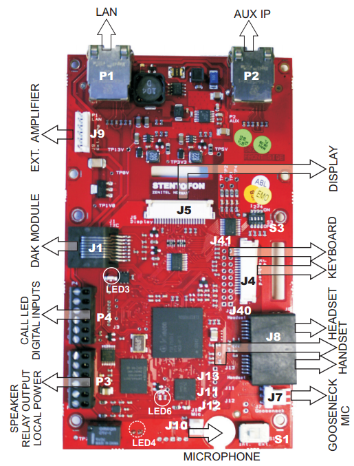
This chapter gives details about connections and indications for:
P1 LAN port & P2 AUX port
P1:
LAN connector for 10/100 Mbit Ethernet connection. The station can be powered from this connection if the line supports Power over Ethernet (PoE).
The connector has two LEDs in front where the right (R) LED indicates Ethernet speed and the left (L) LED verifies Ethernet link and traffic. (L and R as seen from the connector side)
P2:
RJ45 connector for auxiliary equipment like IP camera, PC or a second IP station. This port does not have an individual IP address. It does not carry power for AUX equipment.
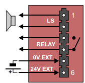
P3 - External Loudspeaker, Relay Output and External Power Input
6-pin plug-on screw terminal for external connections.
- Pin 1/2 Connect to 1.5 W loudspeaker.
- Typical impedance: 8 Ω
- Recommended impedance: 6-25 Ω.
- Pin 3/4 Internal NO relay contact for door lock control etc.
- Pin 5/6 Connect 24 VDC for station power if PoE is not used. Pin 6 is positive.
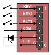
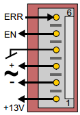
P4 - Inputs and Station LED
6-pin plug-on screw terminal for external connections.
- Pin 1/4 Input 1
- Pin 2/4 Input 2
- Pin 3/4 Input 3
- Pin 5/6 Station LED for call message info.

|
|
J4, J40 & J41 - Keyboard and DAK LED
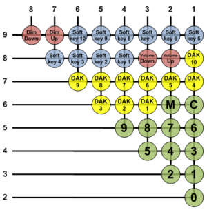
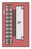
Keyboard matrix is available on connector J4 and on connector J40. Pin 1-9 is used.
In software you can choose between four different matrix types, see Keyboard Settings.
J4 - Keyboard matrix
18-pin ZIF-connector for keyboard. The keyboard may have up to 10 dialling keys, M and C keys, 10 DAK keys, 10 soft keys, volume up/down and light dim up/down keys connected in a matrix according to the drawing.
J40 - Keyboard matrix
J40 provides an optional keyboard connection on a pinheader.
J4 and J41 - DAK LED connection
Optional DAK LED connection. Connection to J40/J41 can either be to a pin header or soldered directly to holes in the PCB.
- J4/10 - J41/1 DAK1 Green LED
- J4/11 - J41/2 DAK1 Red LED
- J4/12 - J41/3 DAK2 Green LED
- J4/13 - J41/4 DAK2 Red LED
- J4/14 - J41/5 DAK3 Green LED
- J4/15 - J41/6 DAK3 Red LED
- J4/16 - J41/7 DAK4 Green LED
- J4/17 - J41/8 DAK4 Red LED
- J4/18 - J41/9 Common +3.3 V
The DAK keys and the DAK LEDs are programmed using IND commands in the Event Handler. DAKs 1 to 4 and Soft keys 1 to 4 are used in current master stations.
Privacy on/off is accomplished by pressing the C key for 2 seconds. A circled P is shown in the display during Privacy mode.
J5 - Display
20-pin ZIF connector for LCD display. Separate display panels are available as a kit of 5 units (order no. 100 8099 000).
J1 - DAK48 Module
RJ45 Connector for I2C interface. Used for connection of DAK modules.
- Pin 1 GND
- Pin 2 A0 (GND)
- Pin 3 A1 (GND)
- Pin 4 NC (GND)
- Pin 5 IRQ
- Pin 6 SCL (Clock)
- Pin 7 SDA (Data)
- Pin 8 +13 V
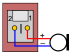
J7 - Gooseneck Microphone
3-pin header for connecting gooseneck microphone.
- Pin 1 MIC+
- Pin 2 MIC-
- Pin 3 GND
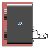
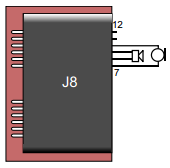
J8 - Handset and Headset
Dual RJ11 for handset and headset. Handset can optionally be connected via J11, J12 and J13.
Handset:
- Pin 1 Mic+
- Pin 2 Spk+
- Pin 3 Spk- (0 V)
- Pin 4 Mic-
- Pin 5 Hook-switch (must be connected to pin 6 via a switch)
- Pin 6 Hook-switch Ground
See also: IP Flush Master and IP Flush Handset compatibility

|
On PCB version 8023 ver.4 and earlier, the Hook-switch had to be connected between pin 5 and 3, not between pin 5 and 6. |
Headset:
- Pin 7 Mic+
- Pin 8 Spk+
- Pin 9 Spk-
- Pin 10 Mic-
- Pin 11 PTT Ground
- Pin 12 PTT (Not currently supported by SW)
J9 - External Amplifier
6-pin header for connecting external amplifier. 12V/5W can be supplied to the external amplifier. Signal to amplifier is balanced 0dBm 600 ohm.
- Pin 1 +13 V max. 500 mA to amplifier
- Pin 2 LSN negative line
- Pin 3 LSP positive line
- Pin 4 GND
- Pin 5 AMP_EN enable signal to amplifier
- Pin 6 AMP_ERR error signal from amplifier
J10 - Microphone
Internal microphone
- Pin 1 MIC+
- Pin 2 MIC-
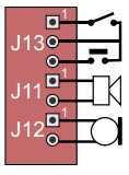
J11, J12 & J13 - Handset
Pin header for handset connection. Same as J8 pin 1 - 6.
- J11 Pin 1 Spk+
- J11 Pin 2 Spk-
- J12 Pin 1 Mic+
- J12 Pin 2 Mic-
- J13 Pin 1 OFFHOOK
- J13 Pin 2 GND
- J13 Pin 3 PTT (Not currently supported by SW)
S1 - Microphone Selection
Slide-switch to select internal microphone (Int) or gooseneck microphone (Ext).
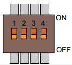
S3 - Future use
4-way DIP switch for future use. Leave all in default OFF position.


