Difference between revisions of "RIO - Remote Input/Output Unit"
From Zenitel Wiki
(→Error dump) |
|||
| (143 intermediate revisions by 4 users not shown) | |||
| Line 1: | Line 1: | ||
| − | + | [[image:99705 RS.jpg|thumb|400px|RIO - Remote Input/Output Unit]] | |
| − | [[image: | ||
| − | == | + | == Highlights== |
| − | * 8 inputs - programmable to normally open or closed | + | * 8 inputs - programmable to normally open or closed |
* 18 outputs | * 18 outputs | ||
| − | * Provides connectors for 3 MRBD Multi-Relay Boards with drivers | + | * Provides connectors for 3 MRBD Multi-Relay Boards with drivers |
* Easy connection in mounting box (included) | * Easy connection in mounting box (included) | ||
| − | * Easy programming of the unit from the AlphaPro programming tool for PC | + | * Easy programming of the unit from the AlphaPro programming tool for PC |
| − | * Connects by RS485 or RS232 to the AlphaCom exchange | + | * Connects by RS485 or RS232 to the AlphaCom exchange |
| − | * When using RS485, up to 10 units can be chained | + | * When using RS485, up to 10 units can be chained |
| − | * With RS485 the maximum distance from the exchange is 1 km | + | * With RS485 the maximum distance from the exchange is 1 km |
| − | * Status LED on the board | + | * Status LED on the board |
* Built-in error indication | * Built-in error indication | ||
| − | * Power must be supplied locally if the RIO unit is mounted outside the exchange room | + | * Power must be supplied locally if the RIO unit is mounted outside the exchange room |
| − | == | + | ==Additional Documentation== |
| − | + | For more documentation please see http://www.zenitel.com/product/product/remote-inputoutput-controller | |
| − | |||
| − | |||
| − | |||
| − | + | == Connectors and Switches == | |
| − | + | === RIO Board === | |
| − | + | [[image:RIO - Remote InputOutput Unit - Connectors and switches on RIO board.jpg|left|thumb|500px|Connectors and switches on RIO board]] | |
| − | + | <br style="clear:both;" /> | |
| − | |||
| − | |||
| − | |||
| − | |||
| − | The RIO is used for:<br> | + | === IIEC Board === |
| − | * | + | [[image:RIO - Remote InputOutput Unit - Connectors on IIEC board.jpg|left|thumb|500px|Connectors on IIEC board]] |
| − | * | + | <br style="clear:both;" /> |
| − | [[Category: | + | |
| + | === Serial Interface setting on the RIO Board - Switch S1: 8 === | ||
| + | [[image:RIO - Remote InputOutput Unit - RIO Switch 1-8.jpg|left|thumb|500px|RIO Switch 1-8]] | ||
| + | <br style="clear:both;" /> | ||
| + | |||
| + | === Address setting - Switch S1:1-6 === | ||
| + | [[image:RIO - Remote InputOutput Unit - Address Switch-settings RIO.jpg|left|thumb|500px|Address Switch-settings RIO]] | ||
| + | <br style="clear:both;" /> | ||
| + | |||
| + | == RS 485 bus == | ||
| + | The RS 485 bus can be maximum 1 km long. Up to 10 RIOs can be connected to the bus. | ||
| + | The data pair must be terminated in each end with a resistor equal to the cable impedance, | ||
| + | typically 150-ohm. | ||
| + | |||
| + | When connecting the RIOs to the bus, wire stubs must be kept as short as possible, | ||
| + | preferably less than 0.5 m. All RIOs must be connected to a common GND reference | ||
| + | conductor. | ||
| + | |||
| + | ''NOTE: Use local power supply for each RIO.'' | ||
| + | |||
| + | ''NOTE: Do NOT use the GND reference for power distribution.'' | ||
| + | |||
| + | [[image:RIO - Remote InputOutput Unit - RS 485 bus overview.jpg|left|thumb|500px|RS 485 bus overview]] | ||
| + | <br style="clear:both;" /> | ||
| + | |||
| + | == Installation == | ||
| + | === General Description === | ||
| + | The RIO unit should be installed in a dry and dust free environment. There is easy access to | ||
| + | connectors and DIP-switches through openings in the front plate. A 15 pin D-sub with 0,5m | ||
| + | of color-coded cable is provided for the RS485 connector. The unit can be mounted to | ||
| + | mounting rails. | ||
| + | |||
| + | The RIO unit can be installed in the following locations: | ||
| + | * At the connection field of the exchange. | ||
| + | * Elsewhere in the same room. | ||
| + | * Up to 1km away through the RS485 bus, with 10 units chained together. | ||
| + | * Up to 50 m away through the RS232 bus. | ||
| + | |||
| + | ''Note: if the RS232 connection is used, surveillance and debugging of the RIO is not possible.'' | ||
| + | |||
| + | === Power supply === | ||
| + | The RIO unit can use power from the exchange if it is installed in the exchange room; | ||
| + | otherwise it must be powered locally. | ||
| + | |||
| + | === Cable requirements === | ||
| + | ==== RS485 ==== | ||
| + | RIO mounted in the exchange room : | ||
| + | * 2 wires for data. | ||
| + | * 2 wires for power from exchange | ||
| + | |||
| + | RIO mounted outside the exchange room: | ||
| + | * 2 wires for data | ||
| + | * 1 wire for ground reference | ||
| + | * 2 wires for local power. | ||
| + | |||
| + | ==== RS232 ==== | ||
| + | * 2 wires for data. | ||
| + | * 1 wire for ground reference | ||
| + | * 2 wires for power from exchange/local power | ||
| + | <br> | ||
| + | |||
| + | [[File:RIO cabling.PNG|left|thumb|500px|Installation of RIO unit in AlphaCom XE]] | ||
| + | <br style="clear:both;" /> | ||
| + | |||
| + | === Installation of the RIO system === | ||
| + | ==== Power supply ==== | ||
| + | If local power is used, a regulated 24VDC /1A power supply is necessary. | ||
| + | |||
| + | ''Note; this is NOT supplied from Stento.'' | ||
| + | |||
| + | If power from the exchange is used, a Power Distribution Board in the exchange is | ||
| + | necessary. | ||
| + | <center><pre>CATION | ||
| + | Do not extend power cables from the PDB outside the exchange rack environment. Use local power for remote installation of equipment. | ||
| + | </pre></center> | ||
| + | |||
| + | [[image:RIO Installation.jpg|left|thumb|500px|]] | ||
| + | <br style="clear:both;" /> | ||
| + | |||
| + | ==== Installing the RIO Unit ==== | ||
| + | The RIO unit is made up of 2 boards, the RIO board and the IICE board. | ||
| + | * Fasten the RIO unit to a mounting rail. | ||
| + | * Supply both boards with +24V and 0V (GND), each board has its own power connector. | ||
| + | A one-pair ordinary installation cable can be used. (Power cable is not supplied.) | ||
| + | |||
| + | * Connect a cable from one of the exchange's RS485 / RS232 ports to the RIO board. There are 3 possible configurations as shown in Figure 6, Figure 7 and Figure 8: | ||
| + | ** A RS485 multidrop bus using power from the exchange, the 0V power connection is also the GND reference for the bus. | ||
| + | ** A RS485 multidrop with local power, then a separate GND reference wire is necessary. With the RS485 it is possible to connect up to ten RIO's to the same bus. This is indicated with the continuing bus, the next RIO will be connected the same way as the one shown. | ||
| + | ** A RS232 point to point with power from the exchange, with the usual TX, RX and GND signals. | ||
| + | A 15-pin D-sub connector with 0,5m cable is provided for connection to the RS485 bus. | ||
| + | ''Note: a 9-pin D-sub for the RS232 connector is NOT provided.'' | ||
| + | |||
| + | * [http://10.5.2.54/wiki/index.php/RIO_-_Remote_Input/Output_Unit#Serial_Interface_setting_on_the_RIO_Board_-_Switch_S1:_8 Check the switch setting] | ||
| + | |||
| + | ==== Installing Multi Relay Board MRBD ==== | ||
| + | If only RIO <u>inputs</u> are used, this board is not necessary. But if RIO <u>outputs</u> are used, MRBD | ||
| + | boards must be connected to provide 6, 12 or 18 relay outputs. | ||
| + | * Fasten the Relay Board beside the RIO Unit. | ||
| + | * Supply the board with 24 V and 0 V (GND) from the same power supply as used for the RIO unit. Use a 1-pair ordinary installation cable for this purpose; the cable is not supplied with the board. | ||
| + | * Connect the RCO output cable between the Relay Board and the RIO. | ||
| + | * On the MRBD-board: Check that the jumpers are in position 2 - 3 on switches S1 to S6. | ||
| + | * Switch the power on. | ||
| + | |||
| + | === Installation Examples === | ||
| + | Figure 6, Figure 7 and Figure 8 show examples where the MRBD board is installed along | ||
| + | with the RIO in order to provide additional RCOs. | ||
| + | |||
| + | ==== Installation of RIO Multidrop with Power from the Exchange ==== | ||
| + | [[image:RIO - Remote InputOutput Unit - Installing the RIO Unit - Power from exchange.jpg|left|thumb|500px|Installing the RIO Unit - Power from exchange]] | ||
| + | <br style="clear:both;" /> | ||
| + | |||
| + | <nowiki>*</nowiki> Port 3 is recommended as this by default is enabled for RIO. | ||
| + | |||
| + | Port 1can also be used but has different pinning. | ||
| + | * Interconnect pin 2 and 11 on Port 1, then connect to RIO pin 9 and 11 | ||
| + | * Interconnect pin 4 and 9 on Port 1, then connect to RIO pin 2 and 4. | ||
| + | <nowiki>* *</nowiki> The power connector on the RIO board may not be mounted on older versions of the RIO. | ||
| + | Power is then connected to the 15 pin d-sub on the RIO: | ||
| + | * +24V to pin 6 and 13 | ||
| + | * GND to pin 5 and 12 | ||
| + | |||
| + | ==== Installation of RIO Multidrop with Local Power ==== | ||
| + | [[image:RIO - Remote InputOutput Unit - Installing the RIO Unit - Local Power.jpg|left|thumb|500px|Installing the RIO Unit - Local Power]] | ||
| + | <br style="clear:both;" /> | ||
| + | |||
| + | <nowiki>*</nowiki> Port 3 is recommended as this by default is enabled for RIO. | ||
| + | |||
| + | Port 1can also be used but has different pinning. | ||
| + | * Interconnect pin 2 and 11 on Port 1, then connect to RIO pin 9 and 11 | ||
| + | * Interconnect pin 4 and 9 on Port 1, then connect to RIO pin 2 and 4. | ||
| + | |||
| + | <nowiki>* *</nowiki> The power connector on the RIO board may not be mounted on older versions of the RIO. Power is then connected to the 15 pin d-sub on the RIO: +24V to pin 6 and 13 GND REF to pin 5 | ||
| + | |||
| + | <nowiki>* * *</nowiki> When using local power, the GND of the local power is connected to the exchange GND via the data cable. Make sure that the GND in the local power is floating to prevent ground loop. | ||
| + | |||
| + | ==== Connection of RIO - Point to Point with Power from the Exchange ==== | ||
| + | [[image:RIO - Remote InputOutput Unit - RIO installation – point to point.jpg|left|thumb|500px|RIO installation – point to point]] | ||
| + | |||
| + | <nowiki>* *</nowiki> The power connector on the RIO board may not be mounted on older versions of the RIO. Power is then connected to the 15 pin d-sub on the RIO:<br> | ||
| + | +24V to pin 6 and 13<br> | ||
| + | GND to pin 5 and 12<br> | ||
| + | <br style="clear:both;" /> | ||
| + | |||
| + | |||
| + | On AlphaCom XE one of the serial ports are available on RJ45 connetor. For connection details, see [[Serial port pinout]] | ||
| + | |||
| + | ==== Connection of RCO ==== | ||
| + | Use the cable supplied with the MRBD-board for the 1:1 connection between the RIO Unit | ||
| + | and the MRBD-board. Each of the 6 relays has 2 changeover contacts. Relay 1 is controlled | ||
| + | by RCO 1; relay 2 by RCO 2 etc. | ||
| + | |||
| + | [[image:RIO - Remote InputOutput Unit - Connection of RCO Output.jpg|left|thumb|500px|Connection of RCO Output]] | ||
| + | <br style="clear:both;" /> | ||
| + | |||
| + | ==== Connection of RCI ==== | ||
| + | Connect the cable from the external dry contact to the RCI input connectors on the RIO | ||
| + | Unit. Keep the cables as short as possible, maximum distance is 3 m. The inputs can be | ||
| + | programmed to be normally open or closed. | ||
| + | |||
| + | [[image:RIO - Remote InputOutput Unit -Connection of RCI Input.jpg|left|thumb|500px|Connection of RCI Input]] | ||
| + | <br style="clear:both;" /> | ||
| + | |||
| + | == Programming == | ||
| + | === General === | ||
| + | The AlphaPro programming tool is used for programming of the AlphaCom exchange. | ||
| + | * Connect the PC to the exchange. | ||
| + | * Start AlphaPro and select the database for this exchange. | ||
| + | * If you do not have the exchange configuration on your PC already, make a Get All from the exchange (this takes approx. 10 - 15 minutes). | ||
| + | * Do the required programming according to the instructions in this chapter. | ||
| + | * Send information to the exchange (Send All or Send Changed). | ||
| + | * Reset the exchange. | ||
| + | |||
| + | === Serial Port Setup === | ||
| + | A serial port to be used for the RIO unit must be defined: | ||
| + | * From the AlphaPro main menu, select Exchange & System → Serial Ports. | ||
| + | * Select from the list box the serial port to use. You can choose between port 1 to 7 by selecting ACDP Link 1 to 7. | ||
| + | ** ACDP Link 1 and 2 can be either RS 232 (point to point) or RS 485 (multidrop) | ||
| + | ** ACDP Link 3 is RS 485 (multidrop) only | ||
| + | ** ACDP Link 4 – 7 is RS 232 (point to point) only | ||
| + | |||
| + | The Serial Port Setup should be: | ||
| + | * Enabled flag checked | ||
| + | * Bit Rate: 9600 | ||
| + | * Parity: None | ||
| + | * Data Bits: 8 | ||
| + | * Stop Bits: 1 | ||
| + | |||
| + | ==== Data Link Options ==== | ||
| + | ===== When RS 485 is used ===== | ||
| + | * Link Type: ISO1745 Multidrop | ||
| + | * Broadcast: disabled | ||
| + | |||
| + | ===== When RS 232 is used ===== | ||
| + | * Link Type: ISO1745 Point to Point | ||
| + | * Broadcast: disabled | ||
| + | |||
| + | By default port 3 (ACDP Link 3) is enabled for multi-drop (RS 485): | ||
| + | |||
| + | [[image:RIO - Remote InputOutput Unit - Programming.PNG|left|thumb|500px|Programming]] | ||
| + | <br style="clear:both;" /> | ||
| + | |||
| + | ''Note: When serial port settings are changed, a reset of the exchange is required after the changes are sent to the exchange.'' | ||
| + | |||
| + | === Define the RIO Unit as a Device === | ||
| + | Every RIO Unit connected to the exchange must have a unique device address. The device | ||
| + | address is between 1 – 64, and is determined by the DIP-switches S1 1-6 on the RIO unit. | ||
| + | Normally you give the first RIO unit address 1, the second one address 2 and so on, but any | ||
| + | address between 1 and 64 can be used. | ||
| + | |||
| + | The device address must also be defined in the software. | ||
| + | |||
| + | * From the AlphaPro main menu, select Exchange & System ➝ Devices. The External Devices window is displayed. The list box will show a list of the 64 possible devices. | ||
| + | * Highlight the device number you have chosen for the RIO unit. | ||
| + | * Select device type and serial port to be used. You may also add a descriptive name (optional). | ||
| + | ** Device Type: Remote I/O | ||
| + | ** Data (ACDP Link): Serial Port 1 to 7 | ||
| + | |||
| + | In the External Devices window, the RIO device 1 is defined on serial port 3: | ||
| + | |||
| + | [[image:RIO - Remote InputOutput Unit - Programming_2.PNG|left|thumb|500px|]] | ||
| + | <br style="clear:both;" /> | ||
| + | |||
| + | If there are more than one RIO unit, highlight the next device number, and set Device Type | ||
| + | to Remote I/O and select the serial port to be used. Continue until all RIO units are defined. | ||
| + | |||
| + | === Define the Remote Control Outputs RCO === | ||
| + | Each RIO unit has 18 outputs (RCOs). The outputs must be defined in the software. You | ||
| + | only need to define the outputs that are to be used. The address is the device number of the | ||
| + | RIO unit. In addition the output number must be defined (1 – 18). | ||
| + | * From the AlphaPro main menu, select ''Exchange & System'' → RCO and the Remote Control Output Window is displayed. | ||
| + | The list box will show a list of the 500 possible RCO’s. By default logical RCO 1 – 138 | ||
| + | are assigned to the internal outputs in the AlphaCom exchange (device 65), but can | ||
| + | instead be used for the RIO unit. Or you might choose to start defining new outputs from | ||
| + | logical RCO 139. | ||
| + | * Select an unused RCO from the listbox, and set the device number identical to the device number of the RIO unit. The pin number must be in the range of 1 to 18. You can also add a Descriptive Name (optional). | ||
| + | In the Remote Control Output Window the logical RCOs 139 – 148 are assigned to RIO | ||
| + | device 1, pin number 1 to 10: | ||
| + | |||
| + | [[image:RIO - Remote InputOutput Unit - Programming_3.PNG|left|thumb|500px|]] | ||
| + | <br style="clear:both;" /> | ||
| + | |||
| + | === Define the Remote Control Inputs RCI === | ||
| + | Each RIO unit has 8 inputs (RCIs). The inputs must be defined in the software. You only | ||
| + | need to define the inputs that are to be used. The inputs are identified by the device number | ||
| + | of the RIO unit and the input number (1 – 8). | ||
| + | * From the AlphaPro main menu, select ''Exchange & System'' → RCI. The Remote Control Inputs window is displayed. The list box will show a list of the 140 possible RCIs. By default logical RCI 1 – 8 are assigned to the internal inputs in the AlphaCom exchange (device 65), but can instead be used for the RIO unit. Or you might choose to start defining new inputs from logical RCI number 9. | ||
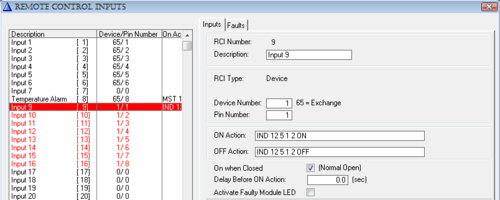
| + | * Select an unused RCI from the listbox, and set the device number identical to the device number of the RIO unit. The pin number must be in the range of 1 to 8. You can also add a Descriptive Name (optional). The Remote Control Inputs window below shows logical RCI 9 – 16 are assigned to RIO device 1, pin number 1 to 8: | ||
| + | |||
| + | [[image:RIO - Remote InputOutput Unit - Programming_4.PNG|left|thumb|500px|]] | ||
| + | <br style="clear:both;" /> | ||
| + | |||
| + | === Assign Functionality to Outputs and Inputs === | ||
| + | In general the outputs (RCO) are given the desired functionality in the Event Handler | ||
| + | programming in AlphaPro. A wide range of events in the AlphaCom exchange can trigger | ||
| + | the RCO. | ||
| + | |||
| + | The inputs (RCI) are given the desired functionality in the RCI programming window. A | ||
| + | wide range of commands is available to start actions in the AlphaCom exchange. | ||
| + | |||
| + | ==== Application Example - Door Opening ==== | ||
| + | In this application example the programming for the Door Opening feature is described. | ||
| + | During conversation between a Control Room station and a Door Station the Control Room | ||
| + | station can press digit 6 to activate an output on the RIO unit. The output activates the door | ||
| + | lock. | ||
| + | |||
| + | If the Control Room station is a CRM-IV station, the status of the door (open or closed) can | ||
| + | be indicated on an LED in the station. There must be a contact at the door that is connected | ||
| + | to the input of the RIO unit. | ||
| + | |||
| + | The example uses: | ||
| + | * Door station number 104 (physical number 4). | ||
| + | * Control room station 112 (physical number 12). | ||
| + | * Logical RCO 139 for door lock. | ||
| + | * Logical RCI 9 for door status indication. | ||
| + | |||
| + | ==== RCO programming ==== | ||
| + | * From the AlphaPro main menu, select ''Users & Stations''. | ||
| + | * Highlight the door station in the list box. | ||
| + | * Go to ''Events''. | ||
| + | * Click '''+''' to define a new event. | ||
| + | * Select: | ||
| + | {| | ||
| + | |+ | ||
| + | | Event Type: | ||
| + | |02 Door Opening – During connection | ||
| + | |- | ||
| + | | When Change To: | ||
| + | |ON or OFF | ||
| + | |- | ||
| + | | When Related To: | ||
| + | |Directory Number 0 | 101 | ||
| + | |- | ||
| + | | Action Command or RCO: | ||
| + | |RCO 139 1/1 | ||
| + | |} | ||
| + | |||
| + | [[image:RIO - Remote InputOutput Unit - Programming_5.PNG|left|thumb|550px|]] | ||
| + | <br style="clear:both;" /> | ||
| + | |||
| + | By this programming only station 101 can activate the door lock. If “When Related To” is | ||
| + | set to '''''All''''', any station in conversation with the door 114 can activate the door lock by | ||
| + | pressing digit 6. | ||
| + | |||
| + | The output will be pulsed for 3,5 seconds when the digit 6 is released. The pulse length can | ||
| + | be changed in ''Exchange & System -> System -> RCO Pulse (Door Open) Time''. | ||
| + | |||
| + | ==== RCI programming ==== | ||
| + | * From the AlphaPro main menu, select ''Exchange & System'' → RCI. | ||
| + | * Highlight the relevant RCI in the list box and define the action command. | ||
| + | |||
| + | [[image:RIO - Remote InputOutput Unit - Programming_6.PNG|left|thumb|500px|]] | ||
| + | <br style="clear:both;" /> | ||
| + | |||
| + | The IND command is used for indication control in the CRM-IV station. | ||
| + | |||
| + | The action: IND 12 5 1 2 ON means: | ||
| + | On physical number 12 - key number 5 - red LED - set flashing – ON. | ||
| + | |||
| + | == Appendix A - Technical Details == | ||
| + | === RIO Cable === | ||
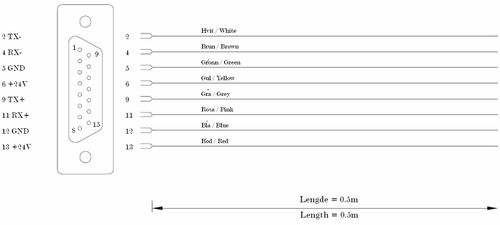
| + | The drawing below shows the color code for the cable included with the RIO Unit. | ||
| + | |||
| + | [[image:RIO - Remote InputOutput Unit - RIO Cable.jpg|left|thumb|500px|]] | ||
| + | <br style="clear:both;" /> | ||
| + | |||
| + | == LED Indication == | ||
| + | The RIO unit is equipped with a Light Emitting Diode LED that shows status information. | ||
| + | This information is quite useful for '''troubleshooting'''. The table below is valid for RIO | ||
| + | software 02.10 and later. | ||
| + | |||
| + | * General status for communication, where red is worse, and green best: | ||
| + | |||
| + | {| Border="1" | ||
| + | |+ | ||
| + | |bgcolor="silver"|LED Status | ||
| + | |bgcolor="silver"|Comment | ||
| + | |- | ||
| + | |fast blinking red | ||
| + | |Power on indication and/or no activity on data line. | ||
| + | |||
| + | − After power on reset of RIO. Implies that the software has started and | ||
| + | works OK so far. No communication with the exchange, i.e. data line has | ||
| + | no activity with any device (which happens when there are no devices on, | ||
| + | or the data wires are broken).<br> | ||
| + | |||
| + | − After a RESET_DEVICE from the exchange, i.e. device initialization either | ||
| + | due to AlphaCom reset, or AlphaCom PONG time-out (2 minutes, this is | ||
| + | the worst-case time you have to wait if you power-up a RIO while the | ||
| + | exchange is running on AMC older than 07.09 (07.30)).<br> | ||
| + | |||
| + | − No polling for more than 15 seconds. I.e. normal operation times out due | ||
| + | to no activity on data line.<br> | ||
| + | |||
| + | − After missing multiple PINGs from the exchange (5 min. time-out), | ||
| + | indicating AlphaCom device handling high-level problem, or no data line | ||
| + | activity (RIO does a software controlled hardware reset) | ||
| + | |- | ||
| + | |slow blinking red | ||
| + | |Some device is being polled, but not this RIO. | ||
| + | |||
| + | − The data connection is electrically OK, but the exchange does not know | ||
| + | this device, or there has been bad communication with this device for | ||
| + | more than 2 minutes. This situation can last for some 40 seconds, and | ||
| + | then the exchange re-tries this RIO again. | ||
| + | |- | ||
| + | |slow blinking amber | ||
| + | |This RIO is being polled by the exchange, but it’s not operational (no RCI/RCO functionality). | ||
| + | |||
| + | − This will occur with AMC versions older than 07.09 (07.30) if the RIO does | ||
| + | a quick reset. There is hope, as the exchange will initialize the RIO after | ||
| + | max. 2 minutes. | ||
| + | |- | ||
| + | |slow blinking green | ||
| + | |Normal operation mode | ||
| + | |||
| + | − After a GET_DEVICE from the exchange, i.e. finalizing of normal | ||
| + | initialization from the AlphaCom | ||
| + | - After a PING from the AlphaCom, indicating that the communication | ||
| + | works OK high-level. | ||
| + | |} | ||
| + | |||
| + | |||
| + | * During normal operation: | ||
| + | Indicate message traffic briefly to give an idea about how many messages are sent, and if | ||
| + | transmission has problems (orange flashes when green blink). | ||
| + | |||
| + | {| border="1" | ||
| + | |+ | ||
| + | |bgcolor="silver"|LED Status | ||
| + | |bgcolor="silver"|Comment | ||
| + | |- | ||
| + | |slow blink amber | ||
| + | |Message in queue to be sent to exchange | ||
| + | − Waiting to be polled | ||
| + | |- | ||
| + | |steady amber | ||
| + | |Message is in being transmitted to the exchange | ||
| + | − Select / send /ACK sequence in progress. | ||
| + | |- | ||
| + | |steady green | ||
| + | |Message received successfully | ||
| + | − ACK received | ||
| + | |- | ||
| + | |steady red | ||
| + | |Message not received/sent successfully | ||
| + | − - NAK / timeout received/sent | ||
| + | |} | ||
| + | |||
| + | Even if there is no RCI/RCO activity, the RIO will PING/PONG with the exchange every 40 | ||
| + | seconds causing LED flashes in amber. | ||
| + | |||
| + | The ACK/NAK indication is reset by the next poll of this device, normally after 50 ms times | ||
| + | the number of devices, sometimes later if there is much message traffic. | ||
| + | |||
| + | * During exceptional hardware states: | ||
| + | |||
| + | Non-operational hardware is indicated using flashing between red and green. | ||
| + | |||
| + | {| border="1" | ||
| + | |+ | ||
| + | |bgcolor="silver"|LED Status | ||
| + | |bgcolor="silver"|Comment | ||
| + | |- | ||
| + | |fast red/green | ||
| + | |Special TEST mode used to activate watchdog | ||
| + | (see description below) | ||
| + | |- | ||
| + | |slow red/green | ||
| + | |Hardware self-test has detected a problem: | ||
| + | - IICB I/O board does not respond, | ||
| + | either due to failure, or the power connector is not in place | ||
| + | |- | ||
| + | |random | ||
| + | red/green/dark | ||
| + | |May occur if the processor does not execute a sensible program, i.e. the | ||
| + | EPROM is dead or missing. On older software without watchdog, electric noise | ||
| + | could make the processor run wild. | ||
| + | |} | ||
| + | |||
| + | ''Note that also the '''terminal''' feature (see Appendix B) is designed to assist installation and maintenance of the multi drop bus, and will present texts indicating the same operational states. The texts will appear every time the LED changes, and also when the “S” (status) command is executed.'' | ||
| + | |||
| + | === Enable Watchdog === | ||
| + | ==== Software ==== | ||
| + | Software versions before 2.12 did not have the internal processor watchdog enabled. | ||
| + | When changing software from an early version to 2.12 or higher, a cold start procedure to | ||
| + | activate the watchdog must be made. See procedure below. | ||
| + | |||
| + | ==== Processor replacement ==== | ||
| + | If the 68HC11 processor must be replaced during service, a cold start procedure to activate | ||
| + | the watchdog must be made. See procedure below. | ||
| + | |||
| + | ==== Watchdog Enable Procedure ==== | ||
| + | The processor 68HC11 comes from factory with the internal COP function (watchdog) | ||
| + | disabled. It must be enabled in a special test mode: | ||
| + | |||
| + | * Power down the RIO, open it and insert new software or replace the processor. | ||
| + | * Connect the two test pins found close to the processor | ||
| + | * Power up the board. The LED will blink red/green | ||
| + | * Power down the board, and remove test pin connection | ||
| + | * Close the RIO mechanics again. Power up, now in operational mode | ||
| + | |||
| + | The terminal function S (status) will show if the Watchdog is active or not. | ||
| + | |||
| + | == Appendix B - RIO Terminal Feature == | ||
| + | === Introduction === | ||
| + | This is an extract from the Application Note “RIO Terminal Feature”. | ||
| + | |||
| + | From version 02.12 the RIO has the possibility to connect a terminal to the 9-pin RS 232 | ||
| + | port, when the RIO is connected to an RS 485-multidrop bus via the 15-pin connector. | ||
| + | |||
| + | The interface is fixed to 9600 baud, 8 bits, no parity, 1 stop bit. | ||
| + | |||
| + | === Functionality RIO Terminal Feature === | ||
| + | The terminal feature is designed to assist installation and maintenance of AlphaCom | ||
| + | multidrop bus devices. | ||
| + | |||
| + | ==== Work with the RIO you are directly connected to, confirming ==== | ||
| + | * DIP-switch settings: | ||
| + | ** You can change the DIP-switch and see the result on-screen immediately. | ||
| + | * RIO operational status: | ||
| + | ** Communication status, and also error counter and traffic counters. | ||
| + | * Watchdog and EEPROM enabled: | ||
| + | ** IICB connection board OK | ||
| + | ** Reset counter plus date/time of last reset. | ||
| + | * RCI configuration: | ||
| + | ** See which pins are monitored by the exchange. | ||
| + | * Dynamic behavior: | ||
| + | ** RCIs are reported. | ||
| + | ** RCOs become set. | ||
| + | |||
| + | ==== Work with the whole bus, monitor by connecting to just one RIO ==== | ||
| + | * Which devices are on the bus: | ||
| + | ** Lists type, software version, and error counters. | ||
| + | * Which devices does the exchange look for on the bus: | ||
| + | ** Have you configured wrong, or are devices missing? | ||
| + | ** Are broadcast messages used? | ||
| + | * All RCI and RCO activity on all RIOs | ||
| + | |||
| + | ==== Log all bus activity over a long period by connecting a PC to one RIO ==== | ||
| + | * Log device resets. | ||
| + | * Log RCI and RCO events. | ||
| + | * Log communication status every hour. | ||
| + | * Log is timestamped with date and time, and each line is identified with node/device number. (Time is received from exchange periodically). | ||
| + | |||
| + | === General === | ||
| + | ==== The Help Menu ==== | ||
| + | Most of the commands are listed by typing '''H<return>'''. | ||
| + | * The commands are single letter commands, some with additional parameters. It may be necessary to type # before the letter. | ||
| + | * Both upper and lowercase letters are accepted. | ||
| + | * Always type <return> to execute the command. | ||
| + | * Note that you get no echo on the screen when you type. The screen will in most cases show a bus trace, i.e. scrolls slowly, so echoing input will be messed up anyway. | ||
| + | |||
| + | <pre> | ||
| + | Commands (no echo): | ||
| + | D -All Devices on bus | ||
| + | I -Display RCIs | ||
| + | O -Display RCOs | ||
| + | Pn -Protocol trace n=1,2,3,4. 0 is OFF | ||
| + | S -Status this RIO | ||
| + | Z -Zero statistics | ||
| + | =+ -Reset | ||
| + | </pre> | ||
| + | |||
| + | The last typed command is always in the buffer, which mans that you can repeat a command | ||
| + | just by typing <return>. After reset it’s set to H. | ||
| + | |||
| + | ==== Trace example ==== | ||
| + | The high-level trace format is: | ||
| + | <pre> | ||
| + | 99-02-02 12:48:25 N1.01 RX SET_RCO 02 00 00 | ||
| + | </pre> | ||
| + | |||
| + | * Time and date yy-mm-dd hh:mm:ss. | ||
| + | * N01.01 means Node 01, Device 01. The numbers are hexadecimal; i.e. the exchange - device 65 - is shown here as 41, and broadcast - 255 - as FF. | ||
| + | * RX/TX indicates the direction of the message; here N01.01 has RECEIVED a message. | ||
| + | * Message text and parameters. The parameters are hexadecimal. | ||
| + | Note that the displayed parameters do not always match the data protocol document. | ||
| + | |||
| + | ==== Introduction to ISO 1745 Data Link ==== | ||
| + | The exchange and the RIO communicate using messages in AlphaCom data protocol format. | ||
| + | The messages are transported to the RIO over ISO 1745, which is a communication protocol | ||
| + | for a multidrop bus. | ||
| + | |||
| + | ==== ISO 1745 Transport ==== | ||
| + | The exchange controls the bus by POLLING each device. Polling is a fast operation where | ||
| + | the exchange transmits 2 digits as device address plus the character <ENQ>, example | ||
| + | 01<ENQ>. The device is now temporarily in control of the bus, and will either respond | ||
| + | with end-of-transmission <EOT> if it has nothing to send, or it will SELECT the destination | ||
| + | by sending a 2 digit device address followed by enquiry, 41<ENQ> (device 41 is the | ||
| + | exchange). | ||
| + | |||
| + | If the receiver is ready, it will acknowledge with <ACK>. The sender then transmits a full | ||
| + | data protocol message, followed by a checksum. The receiver verifies the checksum, and | ||
| + | normally responds <ACK> and then the sender releases control over the bus by sending endof- | ||
| + | transmission <EOT>. If the checksum was wrong, the receives gives a negative acknowledge, <NAK>, which causes the sender to re-transmit, and this goes on until success or 3 attempts has passed. | ||
| + | |||
| + | ==== Application Protocol ==== | ||
| + | The exchange RCI/RCO application has a functional protocol for communication with the | ||
| + | RIO. All messages sent must be acknowledged by a message in the other direction. On top | ||
| + | of ISO 1745 retransmissions, the RIO application in the exchange will do functional | ||
| + | retransmissions after 10 seconds if the acknowledge message does not come. | ||
| + | |||
| + | === Work with local RIO === | ||
| + | There are a number of commands, which give status on the RIO you are connected to at the | ||
| + | moment. | ||
| + | |||
| + | ==== DIP-switc Status Change ==== | ||
| + | You can change the DIP-switch settings and observe the result directly. The RIO reads the | ||
| + | switches once per second, and if a change occurs, it resets to let the new values take effect. | ||
| + | As part of the reset action, the DIP-switch settings are printed out. (If you have connection | ||
| + | with the exchange, there will be some messages related to communication status also…) | ||
| + | |||
| + | <pre> | ||
| + | ==Reset!== Remote I/O Unit Ver 02.12 Build Jan 27 1999 | ||
| + | Device : 1. SW1:7=New,>AMC 06.00. SW1:8=MULTIDROP. | ||
| + | 99-02-02 12:42:33 RIO STATE: Others polled - I'm NOT polled | ||
| + | 99-02-02 12:42:33 RIO STATE: I'm polled (not operational) | ||
| + | 99-02-02 12:42:33 N0.01 TX RESET_TAKEN 00 00 00 | ||
| + | 99-02-02 12:42:33 N1.01 RX RESET_DEVICE 00 00 00 | ||
| + | 99-02-02 12:42:33 RIO STATE: RESET DEVICE - RCI/RCO initialized | ||
| + | 99-02-02 12:42:33 RIO STATE: I'm polled (not operational) | ||
| + | 99-02-02 12:42:34 RIO STATE: I'm polled and operational | ||
| + | 99-02-02 12:42:34 N1.01 RX SET_RCO 07 00 00 | ||
| + | </pre> | ||
| + | |||
| + | Note that if you select SW1:8 as POINT-TO-POINT, the PC will be connected to the RS | ||
| + | 232 port where the AlphaCom is supposed to be. If the RIO receives no ISO1745 data | ||
| + | protocol activity on this port within 15 seconds, it will print a message anyway. | ||
| + | |||
| + | <pre> | ||
| + | Device : 1. SW1:7=New,>=AMC 06.00. SW1:8=POINT-TO-POINT. | ||
| + | </pre> | ||
| + | |||
| + | If SW1:7 is set to the old data protocol format, this causes an error message whenever a | ||
| + | message goes by on the bus: | ||
| + | |||
| + | <pre> | ||
| + | ==Reset!== Remote I/O Unit Ver 02.12 Build Jan 27 1999 | ||
| + | Device : 1. SW1:7=Old,<=AMC 05.00. SW1:8=MULTIDROP. | ||
| + | 99-02-02 12:42:52 RIO STATE: I'm polled (not operational) | ||
| + | 99-02-02 12:42:52 N0.01 TX RESET_TAKEN 00 00 00 | ||
| + | Wrong message format - check SW1:7 against AMC version! | ||
| + | </pre> | ||
| + | |||
| + | ==== RIO Operational Status ==== | ||
| + | You get some status info with the command '''S''': | ||
| + | |||
| + | <pre> | ||
| + | Remote I/O Unit Ver 02.12 Build Jan 27 1999 | ||
| + | Device : 1. SW1:7=New,>=AMC 06.00. SW1:8=MULTIDROP. | ||
| + | RIO STATE: I'm polled and operational | ||
| + | Trace : Application protocol trace (high level) | ||
| + | Resets : 10, last at 1999-02-02 12:43:17 | ||
| + | WatchDog : ACTIVE | ||
| + | I/O board: Operative | ||
| + | Comm. err: 0 in 34 msg (48 msg total) | ||
| + | </pre> | ||
| + | |||
| + | ===== Resets ===== | ||
| + | The RIO stores in its EEPROM a reset counter plus the date/time of the last reset. | ||
| + | Immediately after power-on time is unknown, but is set to the first time message from the | ||
| + | exchange 20 sec. later. | ||
| + | |||
| + | ===== Watchdog ===== | ||
| + | Active / NOT active status. The watchdog is built-in in the microprocessor, and comes from | ||
| + | factory disabled. It has not been used on software prior to RIO 02.12, so if you upgrade in | ||
| + | the field a certain cold start procedure must be performed. You can see here if it’s necessary | ||
| + | to cold-start. | ||
| + | |||
| + | ===== I/O board ===== | ||
| + | The small board along the RIO with input and output connectors is powered with a separate | ||
| + | cable. If power is missing, or the electronics don’t work, you can see it here. This status is | ||
| + | checked by the RIO once per second, and if it fails, the RIO will go into a fault mode where | ||
| + | the exchange will report device error on it. | ||
| + | |||
| + | ===== Comm. errs ===== | ||
| + | Counts number of communication errors in messages to/from this RIO. All messages | ||
| + | to/from this unit is counted and also all messages going to/from all units on the bus. This | ||
| + | gives an indication on bus quality. | ||
| + | |||
| + | ==== RCI Configuration - RCI and RCO Status ==== | ||
| + | In order to use a RIO’s RCI pin successfully, there are several configurations that must be in | ||
| + | place: | ||
| + | * The exchange serial port must be set up for ISO 1745 communication, possibly multidrop mode. Reset is required to activate a serial port protocol. | ||
| + | * The RIO must be defined in the External Devices table as a RIO device, with correct device number on the correct serial port. Reset is NOT required when changing device programming. Use the P3 command (described later) to see immediately if the exchange polls a device or not. | ||
| + | * The pin must be defined in the RCI table. Each time you start using a new pin, the RIO (or the exchange) must be reset to activate the change. | ||
| + | |||
| + | You can see the RIO’s current RCI setting with the '''I''' command: | ||
| + | <pre> | ||
| + | RCI pins: 11111111 | ||
| + | RCI flags: LLLLLNNN | ||
| + | 99-02-02 12:48:25 N1.01 TX RCI_IS_OFF 02 15 00 | ||
| + | RCI pins: 10111111 | ||
| + | RCI flags: LHLLLNNN | ||
| + | </pre> | ||
| + | |||
| + | Explanation: | ||
| + | |||
| + | The “RCI pins” line contains either 0=closed or 1=open for each pin, numbered left to right | ||
| + | 1..8. | ||
| + | The “RCI flags” line contains the AlphaCom’s report mode for each pin. N=No report, | ||
| + | L=Low, H=High. | ||
| + | |||
| + | |||
| + | Use the '''O''' command to see the current status of the '''output pins'''. This is useful if the | ||
| + | controlled equipment does not respond, and you don’t know where to start looking, either to | ||
| + | check exchange programming, or to inspect the wiring. | ||
| + | <pre> | ||
| + | RCO pins: 000000 100000 000000 | ||
| + | 99-02-02 12:48:25 N1.01 RX SET_RCO 02 00 00 | ||
| + | RCO pins: 010000 100000 000000 | ||
| + | </pre> | ||
| + | |||
| + | ===== Message trace ===== | ||
| + | As the examples above indicate you can press RCIs and controls RCOs, and | ||
| + | observe the data protocol messages flowing. The first parameter is the pin number (02 in | ||
| + | the examples). | ||
| + | |||
| + | === Bus monitoring === | ||
| + | The RIO you are connected to can also give information about all the other devices on the | ||
| + | bus. | ||
| + | |||
| + | ==== List devices on the bus ==== | ||
| + | The '''D''' command lists all devices on the bus. This table is built from 3 kinds of messages on | ||
| + | the data line, and you will experience only some fields filled in for long periods. | ||
| + | * Polling, i.e. the exchange addresses each known device in turn, 50 ms between each. | ||
| + | * DEVICE_INFO messages which are sent once after restart. Contains Type and Name. | ||
| + | * PONG messages, which are sent every 40 seconds. Contains SW version and error | ||
| + | statistics. | ||
| + | |||
| + | <pre> | ||
| + | Devices on the bus (40-120 sec. update period): | ||
| + | Dev 01: Operative. Type RIO Ver 02.12 Err 26 Remote I/O Unit | ||
| + | Dev 02: Polled, no answer. | ||
| + | Dev 03: Operative. Type RIO Ver 02.12 Err 3 Remote I/O Unit | ||
| + | </pre> | ||
| + | |||
| + | You get a table of the devices that the exchange tries to address. Note that the device | ||
| + | address is hexadecimal, going from 01 to 1F. Broadcast is FF. | ||
| + | |||
| + | ''NOTE: Avoid broadcast to RIOs.'' | ||
| + | |||
| + | |||
| + | <u>Polled</u> means that the exchange knows about this device in its External Devices table, but | ||
| + | the device has not (yet) answered PONG to a PING message. If the status stays as Polled | ||
| + | for more than 40 seconds, something is wrong. | ||
| + | |||
| + | <u>Operative</u> means that the device responds to PINGs by answering PONG, and that message | ||
| + | contains the SW version and error counter info. Everything is just fine (until you see the | ||
| + | error counter…) | ||
| + | |||
| + | ==== P1 - High-level trace ==== | ||
| + | Command P1 shows a functional trace with timestamps (not all messages are printed). This | ||
| + | is useful when debugging problems related to the configuration of the total system, for | ||
| + | example: Why does RCIs or RCOs fail? | ||
| + | |||
| + | This log uses timestamps, as it may be interesting to use this as a long time log to verify | ||
| + | system operation. When did that alarm RCI go off, and when was that door opened? | ||
| + | <pre> | ||
| + | === Application protocol trace (high level) | ||
| + | RIO STATE: I'm polled and operational | ||
| + | 99-02-02 12:59:21 N1.01 TX RCI_IS_OFF 02 15 00 | ||
| + | 99-02-02 12:59:21 N1.01 RX SET_RCO 02 00 00 | ||
| + | 99-02-02 12:59:22 N1.01 TX RCI_IS_ON 02 0F 00 | ||
| + | </pre> | ||
| + | |||
| + | ==== P2 - Medium-level Trace ==== | ||
| + | Command '''P2''' shows all data protocol messages going on the link. This is useful if you get | ||
| + | error messages to determine exact the occasion when it happens. | ||
| + | <pre> | ||
| + | === Network layer trace (medium level) | ||
| + | RIO STATE: I'm polled and operational | ||
| + | (01)41->(01)01 PING 00 00 00<ACK> | ||
| + | (01)01->(01)41 PONG 02 0C 00<ACK> | ||
| + | (01)01->(01)41 RCI_IS_OFF 02 15 00<ACK> | ||
| + | (01)41->(01)01 SCAN_END_ACK 02 00 00<ACK> | ||
| + | </pre> | ||
| + | |||
| + | ==== P3 - Low-level Trace ==== | ||
| + | Command '''P3''' is a low-level trace of all communication that takes place. Here you can see | ||
| + | the polling of each device, as interpreted by the local RIO. Polling addresses (P01, P02 etc.) | ||
| + | tells you directly which devices the exchange assumes exist on this bus. | ||
| + | |||
| + | <pre> | ||
| + | === ISO data link trace (low level) | ||
| + | RIO STATE: I'm polled and operational | ||
| + | P03,P01,P02,P03,P01,P02,P03,P01,P02,P03,P01,P02,P03,P01,P02,P03, | ||
| + | </pre> | ||
| + | |||
| + | ==== P4 - Character trace ==== | ||
| + | Command '''P4''' is a direct trace of the characters going on the bus. Here you can see if there | ||
| + | is strange characters floating by, which may have been ignored by the higher level, | ||
| + | functional, traces. | ||
| + | |||
| + | <pre> | ||
| + | === Data bus character trace | ||
| + | RIO STATE: I'm polled and operational | ||
| + | tt01qtt02qtt03qtt01qtt02qtt03qtt01qtt02qtt03qtt01qtt02qtt03qtt01 | ||
| + | </pre> | ||
| + | |||
| + | ==== P0 - trace off ==== | ||
| + | To silence the logging, use command P0. It turns all bus monitoring off, except for error | ||
| + | messages. | ||
| + | <pre> | ||
| + | === Data protocol trace OFF | ||
| + | RIO STATE: I'm polled and operational | ||
| + | </pre> | ||
| + | |||
| + | ==== Error dump ==== | ||
| + | When a communication error occurs, you get a time-stamped error message, followed by a | ||
| + | dump of the characters received since last successful message, and in some cases the RIO’s | ||
| + | response to the error. | ||
| + | |||
| + | Example printouts: | ||
| + | <pre> | ||
| + | 99-02-02 13:04:40 ISO FSM: Unexpected <EOT> in state 5 | ||
| + | ISO FSM: 41q01qt | ||
| + | ISO FSM: Delayed 8, Pending 4 | ||
| + | </pre> | ||
| + | |||
| + | <pre> | ||
| + | 99-02-02 12:43:17 ISO FSM: Message received with error: | ||
| + | ISO FSM: >H0141010101410089003C<8 | ||
| + | <=ISO ERR=> | ||
| + | <=NAK=> | ||
| + | </pre> | ||
| + | |||
| + | <pre> | ||
| + | 99-02-02 12:51:07 ISO FSM: Message observed with error: | ||
| + | ISO FSM: 41q03qa>H014101030141008902000020114<N | ||
| + | <=ISO ERR=> | ||
| + | </pre> | ||
| + | |||
| + | [[Category:Additional equipment]] | ||
Latest revision as of 12:58, 3 November 2016
Contents
- 1 Highlights
- 2 Additional Documentation
- 3 Connectors and Switches
- 4 RS 485 bus
- 5 Installation
- 6 Programming
- 7 Appendix A - Technical Details
- 8 LED Indication
- 9 Appendix B - RIO Terminal Feature
Highlights
- 8 inputs - programmable to normally open or closed
- 18 outputs
- Provides connectors for 3 MRBD Multi-Relay Boards with drivers
- Easy connection in mounting box (included)
- Easy programming of the unit from the AlphaPro programming tool for PC
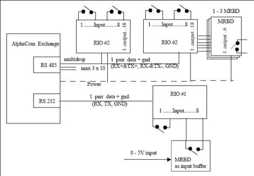
- Connects by RS485 or RS232 to the AlphaCom exchange
- When using RS485, up to 10 units can be chained
- With RS485 the maximum distance from the exchange is 1 km
- Status LED on the board
- Built-in error indication
- Power must be supplied locally if the RIO unit is mounted outside the exchange room
Additional Documentation
For more documentation please see http://www.zenitel.com/product/product/remote-inputoutput-controller
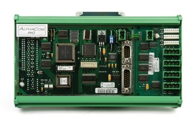
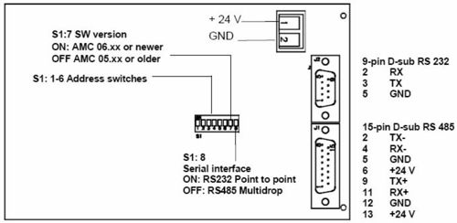
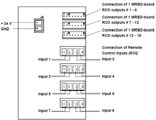
Connectors and Switches
RIO Board
IIEC Board
Serial Interface setting on the RIO Board - Switch S1: 8
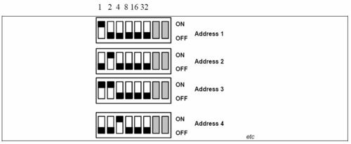
Address setting - Switch S1:1-6
RS 485 bus
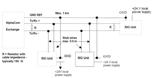
The RS 485 bus can be maximum 1 km long. Up to 10 RIOs can be connected to the bus. The data pair must be terminated in each end with a resistor equal to the cable impedance, typically 150-ohm.
When connecting the RIOs to the bus, wire stubs must be kept as short as possible, preferably less than 0.5 m. All RIOs must be connected to a common GND reference conductor.
NOTE: Use local power supply for each RIO.
NOTE: Do NOT use the GND reference for power distribution.
Installation
General Description
The RIO unit should be installed in a dry and dust free environment. There is easy access to connectors and DIP-switches through openings in the front plate. A 15 pin D-sub with 0,5m of color-coded cable is provided for the RS485 connector. The unit can be mounted to mounting rails.
The RIO unit can be installed in the following locations:
- At the connection field of the exchange.
- Elsewhere in the same room.
- Up to 1km away through the RS485 bus, with 10 units chained together.
- Up to 50 m away through the RS232 bus.
Note: if the RS232 connection is used, surveillance and debugging of the RIO is not possible.
Power supply
The RIO unit can use power from the exchange if it is installed in the exchange room; otherwise it must be powered locally.
Cable requirements
RS485
RIO mounted in the exchange room :
- 2 wires for data.
- 2 wires for power from exchange
RIO mounted outside the exchange room:
- 2 wires for data
- 1 wire for ground reference
- 2 wires for local power.
RS232
- 2 wires for data.
- 1 wire for ground reference
- 2 wires for power from exchange/local power
Installation of the RIO system
Power supply
If local power is used, a regulated 24VDC /1A power supply is necessary.
Note; this is NOT supplied from Stento.
If power from the exchange is used, a Power Distribution Board in the exchange is necessary.
CATION
Do not extend power cables from the PDB outside the exchange rack environment. Use local power for remote installation of equipment.
Installing the RIO Unit
The RIO unit is made up of 2 boards, the RIO board and the IICE board.
- Fasten the RIO unit to a mounting rail.
- Supply both boards with +24V and 0V (GND), each board has its own power connector.
A one-pair ordinary installation cable can be used. (Power cable is not supplied.)
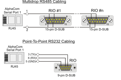
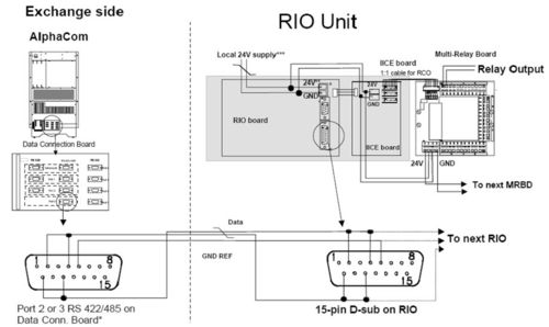
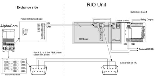
- Connect a cable from one of the exchange's RS485 / RS232 ports to the RIO board. There are 3 possible configurations as shown in Figure 6, Figure 7 and Figure 8:
- A RS485 multidrop bus using power from the exchange, the 0V power connection is also the GND reference for the bus.
- A RS485 multidrop with local power, then a separate GND reference wire is necessary. With the RS485 it is possible to connect up to ten RIO's to the same bus. This is indicated with the continuing bus, the next RIO will be connected the same way as the one shown.
- A RS232 point to point with power from the exchange, with the usual TX, RX and GND signals.
A 15-pin D-sub connector with 0,5m cable is provided for connection to the RS485 bus. Note: a 9-pin D-sub for the RS232 connector is NOT provided.
Installing Multi Relay Board MRBD
If only RIO inputs are used, this board is not necessary. But if RIO outputs are used, MRBD boards must be connected to provide 6, 12 or 18 relay outputs.
- Fasten the Relay Board beside the RIO Unit.
- Supply the board with 24 V and 0 V (GND) from the same power supply as used for the RIO unit. Use a 1-pair ordinary installation cable for this purpose; the cable is not supplied with the board.
- Connect the RCO output cable between the Relay Board and the RIO.
- On the MRBD-board: Check that the jumpers are in position 2 - 3 on switches S1 to S6.
- Switch the power on.
Installation Examples
Figure 6, Figure 7 and Figure 8 show examples where the MRBD board is installed along with the RIO in order to provide additional RCOs.
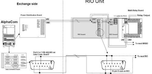
Installation of RIO Multidrop with Power from the Exchange
* Port 3 is recommended as this by default is enabled for RIO.
Port 1can also be used but has different pinning.
- Interconnect pin 2 and 11 on Port 1, then connect to RIO pin 9 and 11
- Interconnect pin 4 and 9 on Port 1, then connect to RIO pin 2 and 4.
* * The power connector on the RIO board may not be mounted on older versions of the RIO. Power is then connected to the 15 pin d-sub on the RIO:
- +24V to pin 6 and 13
- GND to pin 5 and 12
Installation of RIO Multidrop with Local Power
* Port 3 is recommended as this by default is enabled for RIO.
Port 1can also be used but has different pinning.
- Interconnect pin 2 and 11 on Port 1, then connect to RIO pin 9 and 11
- Interconnect pin 4 and 9 on Port 1, then connect to RIO pin 2 and 4.
* * The power connector on the RIO board may not be mounted on older versions of the RIO. Power is then connected to the 15 pin d-sub on the RIO: +24V to pin 6 and 13 GND REF to pin 5
* * * When using local power, the GND of the local power is connected to the exchange GND via the data cable. Make sure that the GND in the local power is floating to prevent ground loop.
Connection of RIO - Point to Point with Power from the Exchange
* * The power connector on the RIO board may not be mounted on older versions of the RIO. Power is then connected to the 15 pin d-sub on the RIO:
+24V to pin 6 and 13
GND to pin 5 and 12
On AlphaCom XE one of the serial ports are available on RJ45 connetor. For connection details, see Serial port pinout
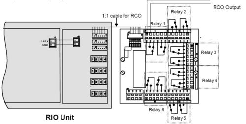
Connection of RCO
Use the cable supplied with the MRBD-board for the 1:1 connection between the RIO Unit and the MRBD-board. Each of the 6 relays has 2 changeover contacts. Relay 1 is controlled by RCO 1; relay 2 by RCO 2 etc.
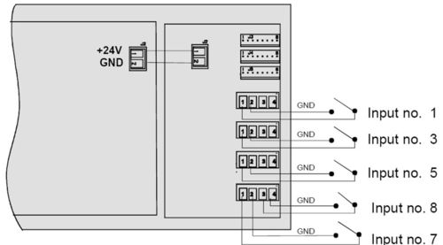
Connection of RCI
Connect the cable from the external dry contact to the RCI input connectors on the RIO Unit. Keep the cables as short as possible, maximum distance is 3 m. The inputs can be programmed to be normally open or closed.
Programming
General
The AlphaPro programming tool is used for programming of the AlphaCom exchange.
- Connect the PC to the exchange.
- Start AlphaPro and select the database for this exchange.
- If you do not have the exchange configuration on your PC already, make a Get All from the exchange (this takes approx. 10 - 15 minutes).
- Do the required programming according to the instructions in this chapter.
- Send information to the exchange (Send All or Send Changed).
- Reset the exchange.
Serial Port Setup
A serial port to be used for the RIO unit must be defined:
- From the AlphaPro main menu, select Exchange & System → Serial Ports.
- Select from the list box the serial port to use. You can choose between port 1 to 7 by selecting ACDP Link 1 to 7.
- ACDP Link 1 and 2 can be either RS 232 (point to point) or RS 485 (multidrop)
- ACDP Link 3 is RS 485 (multidrop) only
- ACDP Link 4 – 7 is RS 232 (point to point) only
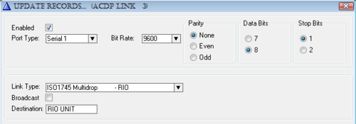
The Serial Port Setup should be:
- Enabled flag checked
- Bit Rate: 9600
- Parity: None
- Data Bits: 8
- Stop Bits: 1
Data Link Options
When RS 485 is used
- Link Type: ISO1745 Multidrop
- Broadcast: disabled
When RS 232 is used
- Link Type: ISO1745 Point to Point
- Broadcast: disabled
By default port 3 (ACDP Link 3) is enabled for multi-drop (RS 485):
Note: When serial port settings are changed, a reset of the exchange is required after the changes are sent to the exchange.
Define the RIO Unit as a Device
Every RIO Unit connected to the exchange must have a unique device address. The device address is between 1 – 64, and is determined by the DIP-switches S1 1-6 on the RIO unit. Normally you give the first RIO unit address 1, the second one address 2 and so on, but any address between 1 and 64 can be used.
The device address must also be defined in the software.
- From the AlphaPro main menu, select Exchange & System ➝ Devices. The External Devices window is displayed. The list box will show a list of the 64 possible devices.
- Highlight the device number you have chosen for the RIO unit.
- Select device type and serial port to be used. You may also add a descriptive name (optional).
- Device Type: Remote I/O
- Data (ACDP Link): Serial Port 1 to 7
In the External Devices window, the RIO device 1 is defined on serial port 3:
If there are more than one RIO unit, highlight the next device number, and set Device Type to Remote I/O and select the serial port to be used. Continue until all RIO units are defined.
Define the Remote Control Outputs RCO
Each RIO unit has 18 outputs (RCOs). The outputs must be defined in the software. You only need to define the outputs that are to be used. The address is the device number of the RIO unit. In addition the output number must be defined (1 – 18).
- From the AlphaPro main menu, select Exchange & System → RCO and the Remote Control Output Window is displayed.
The list box will show a list of the 500 possible RCO’s. By default logical RCO 1 – 138 are assigned to the internal outputs in the AlphaCom exchange (device 65), but can instead be used for the RIO unit. Or you might choose to start defining new outputs from logical RCO 139.
- Select an unused RCO from the listbox, and set the device number identical to the device number of the RIO unit. The pin number must be in the range of 1 to 18. You can also add a Descriptive Name (optional).
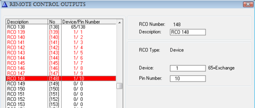
In the Remote Control Output Window the logical RCOs 139 – 148 are assigned to RIO device 1, pin number 1 to 10:
Define the Remote Control Inputs RCI
Each RIO unit has 8 inputs (RCIs). The inputs must be defined in the software. You only need to define the inputs that are to be used. The inputs are identified by the device number of the RIO unit and the input number (1 – 8).
- From the AlphaPro main menu, select Exchange & System → RCI. The Remote Control Inputs window is displayed. The list box will show a list of the 140 possible RCIs. By default logical RCI 1 – 8 are assigned to the internal inputs in the AlphaCom exchange (device 65), but can instead be used for the RIO unit. Or you might choose to start defining new inputs from logical RCI number 9.
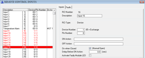
- Select an unused RCI from the listbox, and set the device number identical to the device number of the RIO unit. The pin number must be in the range of 1 to 8. You can also add a Descriptive Name (optional). The Remote Control Inputs window below shows logical RCI 9 – 16 are assigned to RIO device 1, pin number 1 to 8:
Assign Functionality to Outputs and Inputs
In general the outputs (RCO) are given the desired functionality in the Event Handler programming in AlphaPro. A wide range of events in the AlphaCom exchange can trigger the RCO.
The inputs (RCI) are given the desired functionality in the RCI programming window. A wide range of commands is available to start actions in the AlphaCom exchange.
Application Example - Door Opening
In this application example the programming for the Door Opening feature is described. During conversation between a Control Room station and a Door Station the Control Room station can press digit 6 to activate an output on the RIO unit. The output activates the door lock.
If the Control Room station is a CRM-IV station, the status of the door (open or closed) can be indicated on an LED in the station. There must be a contact at the door that is connected to the input of the RIO unit.
The example uses:
- Door station number 104 (physical number 4).
- Control room station 112 (physical number 12).
- Logical RCO 139 for door lock.
- Logical RCI 9 for door status indication.
RCO programming
- From the AlphaPro main menu, select Users & Stations.
- Highlight the door station in the list box.
- Go to Events.
- Click + to define a new event.
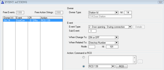
- Select:
| Event Type: | 02 Door Opening – During connection |
| When Change To: | ON or OFF |
| When Related To: | 101 |
| Action Command or RCO: | RCO 139 1/1 |
By this programming only station 101 can activate the door lock. If “When Related To” is set to All, any station in conversation with the door 114 can activate the door lock by pressing digit 6.
The output will be pulsed for 3,5 seconds when the digit 6 is released. The pulse length can be changed in Exchange & System -> System -> RCO Pulse (Door Open) Time.
RCI programming
- From the AlphaPro main menu, select Exchange & System → RCI.
- Highlight the relevant RCI in the list box and define the action command.
The IND command is used for indication control in the CRM-IV station.
The action: IND 12 5 1 2 ON means: On physical number 12 - key number 5 - red LED - set flashing – ON.
Appendix A - Technical Details
RIO Cable
The drawing below shows the color code for the cable included with the RIO Unit.
LED Indication
The RIO unit is equipped with a Light Emitting Diode LED that shows status information. This information is quite useful for troubleshooting. The table below is valid for RIO software 02.10 and later.
- General status for communication, where red is worse, and green best:
| LED Status | Comment |
| fast blinking red | Power on indication and/or no activity on data line.
− After power on reset of RIO. Implies that the software has started and
works OK so far. No communication with the exchange, i.e. data line has
no activity with any device (which happens when there are no devices on,
or the data wires are broken). − After a RESET_DEVICE from the exchange, i.e. device initialization either
due to AlphaCom reset, or AlphaCom PONG time-out (2 minutes, this is
the worst-case time you have to wait if you power-up a RIO while the
exchange is running on AMC older than 07.09 (07.30)). − No polling for more than 15 seconds. I.e. normal operation times out due
to no activity on data line. − After missing multiple PINGs from the exchange (5 min. time-out), indicating AlphaCom device handling high-level problem, or no data line activity (RIO does a software controlled hardware reset) |
| slow blinking red | Some device is being polled, but not this RIO.
− The data connection is electrically OK, but the exchange does not know this device, or there has been bad communication with this device for more than 2 minutes. This situation can last for some 40 seconds, and then the exchange re-tries this RIO again. |
| slow blinking amber | This RIO is being polled by the exchange, but it’s not operational (no RCI/RCO functionality).
− This will occur with AMC versions older than 07.09 (07.30) if the RIO does a quick reset. There is hope, as the exchange will initialize the RIO after max. 2 minutes. |
| slow blinking green | Normal operation mode
− After a GET_DEVICE from the exchange, i.e. finalizing of normal initialization from the AlphaCom - After a PING from the AlphaCom, indicating that the communication works OK high-level. |
- During normal operation:
Indicate message traffic briefly to give an idea about how many messages are sent, and if transmission has problems (orange flashes when green blink).
| LED Status | Comment |
| slow blink amber | Message in queue to be sent to exchange
− Waiting to be polled |
| steady amber | Message is in being transmitted to the exchange
− Select / send /ACK sequence in progress. |
| steady green | Message received successfully
− ACK received |
| steady red | Message not received/sent successfully
− - NAK / timeout received/sent |
Even if there is no RCI/RCO activity, the RIO will PING/PONG with the exchange every 40 seconds causing LED flashes in amber.
The ACK/NAK indication is reset by the next poll of this device, normally after 50 ms times the number of devices, sometimes later if there is much message traffic.
- During exceptional hardware states:
Non-operational hardware is indicated using flashing between red and green.
| LED Status | Comment |
| fast red/green | Special TEST mode used to activate watchdog
(see description below) |
| slow red/green | Hardware self-test has detected a problem:
- IICB I/O board does not respond, either due to failure, or the power connector is not in place |
| random
red/green/dark |
May occur if the processor does not execute a sensible program, i.e. the
EPROM is dead or missing. On older software without watchdog, electric noise could make the processor run wild. |
Note that also the terminal feature (see Appendix B) is designed to assist installation and maintenance of the multi drop bus, and will present texts indicating the same operational states. The texts will appear every time the LED changes, and also when the “S” (status) command is executed.
Enable Watchdog
Software
Software versions before 2.12 did not have the internal processor watchdog enabled. When changing software from an early version to 2.12 or higher, a cold start procedure to activate the watchdog must be made. See procedure below.
Processor replacement
If the 68HC11 processor must be replaced during service, a cold start procedure to activate the watchdog must be made. See procedure below.
Watchdog Enable Procedure
The processor 68HC11 comes from factory with the internal COP function (watchdog) disabled. It must be enabled in a special test mode:
- Power down the RIO, open it and insert new software or replace the processor.
- Connect the two test pins found close to the processor
- Power up the board. The LED will blink red/green
- Power down the board, and remove test pin connection
- Close the RIO mechanics again. Power up, now in operational mode
The terminal function S (status) will show if the Watchdog is active or not.
Appendix B - RIO Terminal Feature
Introduction
This is an extract from the Application Note “RIO Terminal Feature”.
From version 02.12 the RIO has the possibility to connect a terminal to the 9-pin RS 232 port, when the RIO is connected to an RS 485-multidrop bus via the 15-pin connector.
The interface is fixed to 9600 baud, 8 bits, no parity, 1 stop bit.
Functionality RIO Terminal Feature
The terminal feature is designed to assist installation and maintenance of AlphaCom multidrop bus devices.
Work with the RIO you are directly connected to, confirming
- DIP-switch settings:
- You can change the DIP-switch and see the result on-screen immediately.
- RIO operational status:
- Communication status, and also error counter and traffic counters.
- Watchdog and EEPROM enabled:
- IICB connection board OK
- Reset counter plus date/time of last reset.
- RCI configuration:
- See which pins are monitored by the exchange.
- Dynamic behavior:
- RCIs are reported.
- RCOs become set.
Work with the whole bus, monitor by connecting to just one RIO
- Which devices are on the bus:
- Lists type, software version, and error counters.
- Which devices does the exchange look for on the bus:
- Have you configured wrong, or are devices missing?
- Are broadcast messages used?
- All RCI and RCO activity on all RIOs
Log all bus activity over a long period by connecting a PC to one RIO
- Log device resets.
- Log RCI and RCO events.
- Log communication status every hour.
- Log is timestamped with date and time, and each line is identified with node/device number. (Time is received from exchange periodically).
General
The Help Menu
Most of the commands are listed by typing H<return>.
- The commands are single letter commands, some with additional parameters. It may be necessary to type # before the letter.
- Both upper and lowercase letters are accepted.
- Always type <return> to execute the command.
- Note that you get no echo on the screen when you type. The screen will in most cases show a bus trace, i.e. scrolls slowly, so echoing input will be messed up anyway.
Commands (no echo):
D -All Devices on bus
I -Display RCIs
O -Display RCOs
Pn -Protocol trace n=1,2,3,4. 0 is OFF
S -Status this RIO
Z -Zero statistics
=+ -Reset
The last typed command is always in the buffer, which mans that you can repeat a command just by typing <return>. After reset it’s set to H.
Trace example
The high-level trace format is:
99-02-02 12:48:25 N1.01 RX SET_RCO 02 00 00
- Time and date yy-mm-dd hh:mm:ss.
- N01.01 means Node 01, Device 01. The numbers are hexadecimal; i.e. the exchange - device 65 - is shown here as 41, and broadcast - 255 - as FF.
- RX/TX indicates the direction of the message; here N01.01 has RECEIVED a message.
- Message text and parameters. The parameters are hexadecimal.
Note that the displayed parameters do not always match the data protocol document.
Introduction to ISO 1745 Data Link
The exchange and the RIO communicate using messages in AlphaCom data protocol format. The messages are transported to the RIO over ISO 1745, which is a communication protocol for a multidrop bus.
ISO 1745 Transport
The exchange controls the bus by POLLING each device. Polling is a fast operation where the exchange transmits 2 digits as device address plus the character <ENQ>, example 01<ENQ>. The device is now temporarily in control of the bus, and will either respond with end-of-transmission <EOT> if it has nothing to send, or it will SELECT the destination by sending a 2 digit device address followed by enquiry, 41<ENQ> (device 41 is the exchange).
If the receiver is ready, it will acknowledge with <ACK>. The sender then transmits a full data protocol message, followed by a checksum. The receiver verifies the checksum, and normally responds <ACK> and then the sender releases control over the bus by sending endof- transmission <EOT>. If the checksum was wrong, the receives gives a negative acknowledge, <NAK>, which causes the sender to re-transmit, and this goes on until success or 3 attempts has passed.
Application Protocol
The exchange RCI/RCO application has a functional protocol for communication with the RIO. All messages sent must be acknowledged by a message in the other direction. On top of ISO 1745 retransmissions, the RIO application in the exchange will do functional retransmissions after 10 seconds if the acknowledge message does not come.
Work with local RIO
There are a number of commands, which give status on the RIO you are connected to at the moment.
DIP-switc Status Change
You can change the DIP-switch settings and observe the result directly. The RIO reads the switches once per second, and if a change occurs, it resets to let the new values take effect. As part of the reset action, the DIP-switch settings are printed out. (If you have connection with the exchange, there will be some messages related to communication status also…)
==Reset!== Remote I/O Unit   Ver 02.12 Build Jan 27 1999
Device  : 1. SW1:7=New,>AMC 06.00. SW1:8=MULTIDROP.
99-02-02 12:42:33 RIO STATE: Others polled - I'm NOT polled
99-02-02 12:42:33 RIO STATE: I'm polled (not operational)
99-02-02 12:42:33 N0.01 TX RESET_TAKEN    00 00 00
99-02-02 12:42:33 N1.01 RX RESET_DEVICE   00 00 00
99-02-02 12:42:33 RIO STATE: RESET DEVICE - RCI/RCO initialized
99-02-02 12:42:33 RIO STATE: I'm polled (not operational)
99-02-02 12:42:34 RIO STATE: I'm polled and operational
99-02-02 12:42:34 N1.01 RX SET_RCO        07 00 00
Note that if you select SW1:8 as POINT-TO-POINT, the PC will be connected to the RS 232 port where the AlphaCom is supposed to be. If the RIO receives no ISO1745 data protocol activity on this port within 15 seconds, it will print a message anyway.
Device : 1. SW1:7=New,>=AMC 06.00. SW1:8=POINT-TO-POINT.
If SW1:7 is set to the old data protocol format, this causes an error message whenever a message goes by on the bus:
==Reset!== Remote I/O Unit   Ver 02.12 Build Jan 27 1999
Device   : 1. SW1:7=Old,<=AMC 05.00. SW1:8=MULTIDROP.
99-02-02 12:42:52 RIO STATE: I'm polled (not operational)
99-02-02 12:42:52 N0.01 TX RESET_TAKEN   00 00 00
Wrong message format - check SW1:7 against AMC version!
RIO Operational Status
You get some status info with the command S:
Remote I/O Unit Ver 02.12 Build Jan 27 1999
Device : 1. SW1:7=New,>=AMC 06.00. SW1:8=MULTIDROP.
RIO STATE: I'm polled and operational
Trace : Application protocol trace (high level)
Resets : 10, last at 1999-02-02 12:43:17
WatchDog : ACTIVE
I/O board: Operative
Comm. err: 0 in 34 msg (48 msg total)
Resets
The RIO stores in its EEPROM a reset counter plus the date/time of the last reset. Immediately after power-on time is unknown, but is set to the first time message from the exchange 20 sec. later.
Watchdog
Active / NOT active status. The watchdog is built-in in the microprocessor, and comes from factory disabled. It has not been used on software prior to RIO 02.12, so if you upgrade in the field a certain cold start procedure must be performed. You can see here if it’s necessary to cold-start.
I/O board
The small board along the RIO with input and output connectors is powered with a separate cable. If power is missing, or the electronics don’t work, you can see it here. This status is checked by the RIO once per second, and if it fails, the RIO will go into a fault mode where the exchange will report device error on it.
Comm. errs
Counts number of communication errors in messages to/from this RIO. All messages to/from this unit is counted and also all messages going to/from all units on the bus. This gives an indication on bus quality.
RCI Configuration - RCI and RCO Status
In order to use a RIO’s RCI pin successfully, there are several configurations that must be in place:
- The exchange serial port must be set up for ISO 1745 communication, possibly multidrop mode. Reset is required to activate a serial port protocol.
- The RIO must be defined in the External Devices table as a RIO device, with correct device number on the correct serial port. Reset is NOT required when changing device programming. Use the P3 command (described later) to see immediately if the exchange polls a device or not.
- The pin must be defined in the RCI table. Each time you start using a new pin, the RIO (or the exchange) must be reset to activate the change.
You can see the RIO’s current RCI setting with the I command:
RCI pins: 11111111
RCI flags: LLLLLNNN
99-02-02 12:48:25 N1.01 TX RCI_IS_OFF 02 15 00
RCI pins: 10111111
RCI flags: LHLLLNNN
Explanation:
The “RCI pins” line contains either 0=closed or 1=open for each pin, numbered left to right 1..8. The “RCI flags” line contains the AlphaCom’s report mode for each pin. N=No report, L=Low, H=High.
Use the O command to see the current status of the output pins. This is useful if the
controlled equipment does not respond, and you don’t know where to start looking, either to
check exchange programming, or to inspect the wiring.
RCO pins: 000000 100000 000000
99-02-02 12:48:25 N1.01 RX SET_RCO 02 00 00
RCO pins: 010000 100000 000000
Message trace
As the examples above indicate you can press RCIs and controls RCOs, and observe the data protocol messages flowing. The first parameter is the pin number (02 in the examples).
Bus monitoring
The RIO you are connected to can also give information about all the other devices on the bus.
List devices on the bus
The D command lists all devices on the bus. This table is built from 3 kinds of messages on the data line, and you will experience only some fields filled in for long periods.
- Polling, i.e. the exchange addresses each known device in turn, 50 ms between each.
- DEVICE_INFO messages which are sent once after restart. Contains Type and Name.
- PONG messages, which are sent every 40 seconds. Contains SW version and error
statistics.
Devices on the bus (40-120 sec. update period):
Dev 01: Operative. Type RIO Ver 02.12 Err 26 Remote I/O Unit
Dev 02: Polled, no answer.
Dev 03: Operative. Type RIO Ver 02.12 Err 3 Remote I/O Unit
You get a table of the devices that the exchange tries to address. Note that the device address is hexadecimal, going from 01 to 1F. Broadcast is FF.
NOTE: Avoid broadcast to RIOs.
Polled means that the exchange knows about this device in its External Devices table, but
the device has not (yet) answered PONG to a PING message. If the status stays as Polled
for more than 40 seconds, something is wrong.
Operative means that the device responds to PINGs by answering PONG, and that message contains the SW version and error counter info. Everything is just fine (until you see the error counter…)
P1 - High-level trace
Command P1 shows a functional trace with timestamps (not all messages are printed). This is useful when debugging problems related to the configuration of the total system, for example: Why does RCIs or RCOs fail?
This log uses timestamps, as it may be interesting to use this as a long time log to verify system operation. When did that alarm RCI go off, and when was that door opened?
=== Application protocol trace (high level)
RIO STATE: I'm polled and operational
99-02-02 12:59:21 N1.01 TX RCI_IS_OFF 02 15 00
99-02-02 12:59:21 N1.01 RX SET_RCO 02 00 00
99-02-02 12:59:22 N1.01 TX RCI_IS_ON 02 0F 00
P2 - Medium-level Trace
Command P2 shows all data protocol messages going on the link. This is useful if you get error messages to determine exact the occasion when it happens.
=== Network layer trace (medium level)
RIO STATE: I'm polled and operational
(01)41->(01)01 PING 00 00 00<ACK>
(01)01->(01)41 PONG 02 0C 00<ACK>
(01)01->(01)41 RCI_IS_OFF 02 15 00<ACK>
(01)41->(01)01 SCAN_END_ACK 02 00 00<ACK>
P3 - Low-level Trace
Command P3 is a low-level trace of all communication that takes place. Here you can see the polling of each device, as interpreted by the local RIO. Polling addresses (P01, P02 etc.) tells you directly which devices the exchange assumes exist on this bus.
=== ISO data link trace (low level)
RIO STATE: I'm polled and operational
P03,P01,P02,P03,P01,P02,P03,P01,P02,P03,P01,P02,P03,P01,P02,P03,
P4 - Character trace
Command P4 is a direct trace of the characters going on the bus. Here you can see if there is strange characters floating by, which may have been ignored by the higher level, functional, traces.
=== Data bus character trace
RIO STATE: I'm polled and operational
tt01qtt02qtt03qtt01qtt02qtt03qtt01qtt02qtt03qtt01qtt02qtt03qtt01
P0 - trace off
To silence the logging, use command P0. It turns all bus monitoring off, except for error messages.
=== Data protocol trace OFF
RIO STATE: I'm polled and operational
Error dump
When a communication error occurs, you get a time-stamped error message, followed by a dump of the characters received since last successful message, and in some cases the RIO’s response to the error.
Example printouts:
99-02-02 13:04:40 ISO FSM: Unexpected <EOT> in state 5
ISO FSM: 41q01qt
ISO FSM: Delayed 8, Pending 4
99-02-02 12:43:17 ISO FSM: Message received with error:
ISO FSM: >H0141010101410089003C<8
<=ISO ERR=>
<=NAK=>
99-02-02 12:51:07 ISO FSM: Message observed with error:
ISO FSM: 41q03qa>H014101030141008902000020114<N
<=ISO ERR=>

