Difference between revisions of "AlphaCom Audio Switching Hardware"
From Zenitel Wiki
(→Voice Paging) |
m (60 revisions imported) |
||
| (30 intermediate revisions by 6 users not shown) | |||
| Line 1: | Line 1: | ||
| + | {{A}} | ||
This article contains a brief overview of the hardware involved in audio switching in an AlphaCom Exchange Module. | This article contains a brief overview of the hardware involved in audio switching in an AlphaCom Exchange Module. | ||
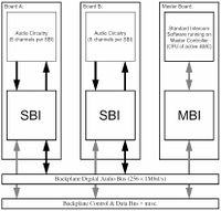
== Audio Switching Hardware Infrastructure Overview == | == Audio Switching Hardware Infrastructure Overview == | ||
| − | [[Image: Audio Switching Hardware Infrastructure Overview.jpg|right|200px|thumb]] | + | [[Image: Audio Switching Hardware Infrastructure Overview.jpg|right|200px|thumb|Hardware Infrastructure Overview ]] |
The first figure below shows the core elements of the infrasructure involved in audio switching. (Non-audio elements such as Slave Controllers are not shown. That the Master board also doubles as a Audio | The first figure below shows the core elements of the infrasructure involved in audio switching. (Non-audio elements such as Slave Controllers are not shown. That the Master board also doubles as a Audio | ||
| Line 12: | Line 13: | ||
Exchange Module. The default modulation is Stentofon-modified 1Msample/s Σ∆-modulation.(Audio with different modulations and synchronous or asynchronous data may be line-switched through the same | Exchange Module. The default modulation is Stentofon-modified 1Msample/s Σ∆-modulation.(Audio with different modulations and synchronous or asynchronous data may be line-switched through the same | ||
infrastructure as well.) | infrastructure as well.) | ||
| − | <br | + | <br /><br /> |
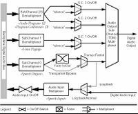
| − | [[Image: Audio Switching Hardware Infrastructure Overview2.jpg|left|200px|thumb]] | + | [[Image: Audio Switching Hardware Infrastructure Overview2.jpg|left|200px|thumb|Structure of SBI Digital Audio Channel]] |
The structure of each SBI Digital Audio Channel is shown in the figure below. Each of the SubChannel | The structure of each SBI Digital Audio Channel is shown in the figure below. Each of the SubChannel | ||
Time/Space Demultiplexers pick out one of the 256 possible signals on the Backplane Digital Audio | Time/Space Demultiplexers pick out one of the 256 possible signals on the Backplane Digital Audio | ||
| Line 27: | Line 28: | ||
the Backplane Digital Audio Bus.(In order to provide a common feeding/fading point for multiple destinations and/or to provide click-free fading to | the Backplane Digital Audio Bus.(In order to provide a common feeding/fading point for multiple destinations and/or to provide click-free fading to | ||
signals destined for faderless subchannels.) | signals destined for faderless subchannels.) | ||
| − | <br | + | <br /><br /> |
Sometimes you will see the subchannels identified by their primary use instead of their number. These | Sometimes you will see the subchannels identified by their primary use instead of their number. These | ||
names are those that look like this in the figure above: «Speech Output». Each of the SubChannel Demultiplexers | names are those that look like this in the figure above: «Speech Output». Each of the SubChannel Demultiplexers | ||
| Line 35: | Line 36: | ||
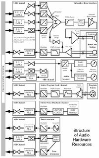
== Structure of Audio Hardware Resources == | == Structure of Audio Hardware Resources == | ||
| − | [[Image: Structure of Audio Hardware Resources.jpg|right|200px|thumb]] | + | [[Image: Structure of Audio Hardware Resources.jpg|right|200px|thumb|Structure of Audio Hardware Resources]] |
The figure below shows the internal structure of all the Audio Hardware Resources. Unused elements, | The figure below shows the internal structure of all the Audio Hardware Resources. Unused elements, | ||
Non-Audio elements and Non-Functional elements are omitted to improve readability. For example | Non-Audio elements and Non-Functional elements are omitted to improve readability. For example | ||
| Line 58: | Line 59: | ||
which type they are (by referring to the Audio Resource descriptions). The brackets and signal- or | which type they are (by referring to the Audio Resource descriptions). The brackets and signal- or | ||
function names show which parts of the topology are established and teared-down by which TO_IF | function names show which parts of the topology are established and teared-down by which TO_IF | ||
| − | input signals or AS_API functions. | + | input signals or AS_API functions. |
| − | |||
=== Normal Tones to Stations === | === Normal Tones to Stations === | ||
| − | [[Image: Normal Tones to Stations.jpg|left|200px|thumb]] | + | [[Image: Normal Tones to Stations.jpg|left|200px|thumb|Normal tones to station]] |
| − | [[Image: Normal Tones to Stations2.jpg|left|200px|thumb]] | + | [[Image: Normal Tones to Stations2.jpg|left|200px|thumb|Muted tones to station]] |
Normal tones are all standard tones except Gong and DTMF but including the two muted (attenuated) | Normal tones are all standard tones except Gong and DTMF but including the two muted (attenuated) | ||
| Line 75: | Line 75: | ||
Muted tone to a Muted tone would have been connected instead. Tone Handling for Normal tones | Muted tone to a Muted tone would have been connected instead. Tone Handling for Normal tones | ||
involves nothing but Audio Switching (except for configuring the Dial-Tone Generator at reset (1)). | involves nothing but Audio Switching (except for configuring the Dial-Tone Generator at reset (1)). | ||
| + | <br/><br/><br/><br/> | ||
| − | === Stored Voice Playback to Stations === | + | === Stored Voice Playback (ASVP) to Stations === |
| − | [[Image: Stored Voice Playback to Stations.jpg|right|200px|thumb]] | + | [[Image: Stored Voice Playback to Stations.jpg|right|200px|thumb|Stored Voice Playback to Stations]] |
Used for Pre-Recorded Help-Messages and Mail-Messages. Connection and disconnection (1) are | Used for Pre-Recorded Help-Messages and Mail-Messages. Connection and disconnection (1) are | ||
done dynamically. Only one Station will receive tone audio from the same SVP Timeslot at a time | done dynamically. Only one Station will receive tone audio from the same SVP Timeslot at a time | ||
| Line 84: | Line 85: | ||
=== Audio Program to Stations === | === Audio Program to Stations === | ||
| − | [[Image: Audio Program to Stations.jpg|right|300px|thumb]] | + | [[Image: Audio Program to Stations.jpg|right|300px|thumb|Audio Program to station]] |
Connection and disconnection of Audio Program Feed Channels to/from Program Timeslots (1) is | Connection and disconnection of Audio Program Feed Channels to/from Program Timeslots (1) is | ||
done dynamically as the program feeds become available (after module or board reset) or unavailable | done dynamically as the program feeds become available (after module or board reset) or unavailable | ||
| Line 95: | Line 96: | ||
=== Two-Party Conversations === | === Two-Party Conversations === | ||
| − | [[Image: Two-Party Conversations.jpg|left|200px|thumb]] | + | [[Image: Two-Party Conversations.jpg|left|200px|thumb|Two-party conversation]] |
Connection and disconnection of Subscriber Line Interfaces (and thereby Stations) (1) and connection | Connection and disconnection of Subscriber Line Interfaces (and thereby Stations) (1) and connection | ||
and disconnection of Audio Scanners (2) are done in the topology shown in the figure. The Audio | and disconnection of Audio Scanners (2) are done in the topology shown in the figure. The Audio | ||
| Line 111: | Line 112: | ||
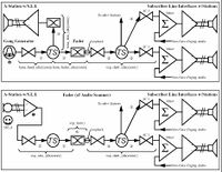
=== Voice Paging === | === Voice Paging === | ||
| − | [[Image: Voice Paiging.jpg| | + | [[Image: Voice Paiging.jpg|right|200px|thumb|Voice paging]] |
Connection of the Gong Generator to the Gong Timeslot (1) is done at reset time together with the | Connection of the Gong Generator to the Gong Timeslot (1) is done at reset time together with the | ||
normal tones as described above, while the rest of the Audio Switching for Voice Paging is done | normal tones as described above, while the rest of the Audio Switching for Voice Paging is done | ||
| − | dynamically. Connecting and disconnecing the Fader(A | + | dynamically. Connecting and disconnecing the Fader(A [[Fader Resource]] is a SBI Channel of an Audio Scanner set in Loopback mode.) via a Timeslot to/from the Audio Program |
SubChannel (2) of the Subscriber Line Interfaces (2) of the stations in the actual Voice Paging Group | SubChannel (2) of the Subscriber Line Interfaces (2) of the stations in the actual Voice Paging Group | ||
are done as the first and last step of a group/all call. The Fader is then used as a common feed point to | are done as the first and last step of a group/all call. The Fader is then used as a common feed point to | ||
| Line 129: | Line 130: | ||
=== Simplex “Program” Conferences === | === Simplex “Program” Conferences === | ||
| − | + | [[Image: Simplex “Program” Conferences.jpg|left|300px|thumb|Simplex Conference]] | |
When the first Subscriber enters the Conference, The Fader (Scanner) is set in Loopback Mode (1) | When the first Subscriber enters the Conference, The Fader (Scanner) is set in Loopback Mode (1) | ||
and Connected to the Distribution Timeslot (2) and the Microphone Timeslot (3), without fading in. | and Connected to the Distribution Timeslot (2) and the Microphone Timeslot (3), without fading in. | ||
| Line 142: | Line 143: | ||
done in the opposite order. Who, if any, is to speak is determined by M-key use and exchange configuration | done in the opposite order. Who, if any, is to speak is determined by M-key use and exchange configuration | ||
options (default member++). | options (default member++). | ||
| + | |||
| + | [[Category:AlphaCom Hardware]] | ||
Latest revision as of 13:24, 5 February 2018
This article contains a brief overview of the hardware involved in audio switching in an AlphaCom Exchange Module.
Contents
Audio Switching Hardware Infrastructure Overview
The first figure below shows the core elements of the infrasructure involved in audio switching. (Non-audio elements such as Slave Controllers are not shown. That the Master board also doubles as a Audio
Board is not shown here either.) All audio switching is controlled from the software on the Master Controller. It accesses the Audio Switching
Control Registers in the SBI through the MBI and the Backplane Data Bus. Each board may have
from one to eight SBI’s and each SBI has eight identical “Digital Audio Channels” or “Channels” for
short. Audio travels through the system as 1Mbit/s line-switched digital signals. The backplane has 16
bus lines, each with 16 timeslots, giving a total switching capacity of 256 one-way audio signals per
Exchange Module. The default modulation is Stentofon-modified 1Msample/s Σ∆-modulation.(Audio with different modulations and synchronous or asynchronous data may be line-switched through the same
infrastructure as well.)
The structure of each SBI Digital Audio Channel is shown in the figure below. Each of the SubChannel
Time/Space Demultiplexers pick out one of the 256 possible signals on the Backplane Digital Audio
Bus. The third demultiplexed signal is splitted into 2 signals on the Digital Audio Output. Each of the
resulting 4 SubChannels have its separate On/Off control. The Primary (#0) SubChannel has a Fast
(≈8ms) Fader instead of a direct switch to provide click-free switching. (The Fader may be bypassed
in order to transparently forward audio with different modulations or data by sett ing theTransparent/
Faded Mode switch to Transparent). The Digital Audio Output is 8-way time division (TDM) multiplexed,
providing the 4 available Digital Audio Output SubChannels plus 4 channels reserved for
future use. The Digital Audio Input is non-multiplexed. It is put onto the Backplane Digital Audio Bus
by the Audio Input Time/Space Multiplexer if and when the Audio Input On/Off Switch is set to On. It
is possible by setting the Loopback/Normal to Loopback to feed the SubChannel 0 Signal back onto
the Backplane Digital Audio Bus.(In order to provide a common feeding/fading point for multiple destinations and/or to provide click-free fading to
signals destined for faderless subchannels.)
Sometimes you will see the subchannels identified by their primary use instead of their number. These
names are those that look like this in the figure above: «Speech Output». Each of the SubChannel Demultiplexers
and the Audio Input Multiplexer is controlled by a value in a separate 8-bit Timeslot Register
selecting which Backplane Timeslot to listen to or to drive. Each of the On/Off (and Fade In/Out) controls is controlled by a separate bit in a common Channel Control Register. The two mode settings (Transparent/Faded and Loopback/Normal) are controlled by two bits of the Channel Mode Register.
Structure of Audio Hardware Resources
The figure below shows the internal structure of all the Audio Hardware Resources. Unused elements, Non-Audio elements and Non-Functional elements are omitted to improve readability. For example the Subchannel Multiplexers and Subchannel Demultiplexers are omitted since they are non-functional and their inclusion would only have decreased clarity and readability. Some minor details are also omitted since they would have confused the big picture more than clarified it. All non-SBI symbols are supplied with names/descriptions. “Amp.” is short for Amplifier. ADC is an acronym for Analog to Digital Conversion. See the «Audio Switching Hardware Infrastructure Overview» section in the «Audio Switching Architecture» part for details on the SBI Channels. If anything still is unclear refer to the System Architecture Descriptions and Hardware Descriptions (and inform the author if you think it should also be better desribed here).
Audio Switching Hardware Interconnection Topologies
The following subsections show briefly how the different Audio Resources are interconnected by the Audio Switching for different applications (uses). Faders and switches are turned on (or faded in) as part of the establishing of the topology and switched off (faded out) at tear-down unless othervise noted. The topology figures of the following subsections are further simplified relative to the structure diagrams for the audio resources above by omitting Modulators/Demodulators, Timeslot Multiplexers/ Demultiplexers and non-vital (in the respective context) audio elements.TS is used to represent a single Timeslot on the Backplane Digital Audio Bus. Faders and Switches are not marked when it is obvious which type they are (by referring to the Audio Resource descriptions). The brackets and signal- or function names show which parts of the topology are established and teared-down by which TO_IF input signals or AS_API functions.
Normal Tones to Stations
Normal tones are all standard tones except Gong and DTMF but including the two muted (attenuated)
variants. Connection of Tone Generators (1) and Tone Attenuators (2) to Tone Timeslots is done at
reset time for the sake of simplicity and stay connected until the next reset. It is of cause possible to do this dynamically, but that would only create new problens and solve no old ones. Therefore only connecting
and disconnecing Tone Timeslots to/from the (Primary SubChannel of the) Subscriber Line Interfaces
(3) is done dynamically. More than one Station (or no Station at all) may of cause receive tone audio
from the same Tone Timeslot simultaneously. Muted (attenuated) variants of tones are generated by
feeding audio from the Tone Timeslot of the corresponding Non-Muted tone to a Tone Attenuator and
from it to a new Tone Timeslot. The dotted line in the figure below shows how the corresponding Non-
Muted tone to a Muted tone would have been connected instead. Tone Handling for Normal tones
involves nothing but Audio Switching (except for configuring the Dial-Tone Generator at reset (1)).
Stored Voice Playback (ASVP) to Stations
Used for Pre-Recorded Help-Messages and Mail-Messages. Connection and disconnection (1) are done dynamically. Only one Station will receive tone audio from the same SVP Timeslot at a time (with the currently implemented services). Playback of Stored Voice Messages involves only Playback Control (2) for the Stored Voice Playback Channel in addition to Audio Switching.
Audio Program to Stations
Connection and disconnection of Audio Program Feed Channels to/from Program Timeslots (1) is done dynamically as the program feeds become available (after module or board reset) or unavailable (when an individual board fails or is reset). Connecting and Disconnecting Program Timeslots to the Audio Program SubChannel (2) of the Subscriber Line Interfaces (and thereby Stations (2)) are always done dynamically, caused by manual (de)activation, automatic (de)activation or temporary masking when the station is busy. More than one Station (or no Station at all) may of cause receive program audio from the same Audio Program Timeslot simultaneously. Audio Program Handling involves nothing but Audio Switching. (The Gain Control and the Program Source are adjusted manually).
Two-Party Conversations
Connection and disconnection of Subscriber Line Interfaces (and thereby Stations) (1) and connection and disconnection of Audio Scanners (2) are done in the topology shown in the figure. The Audio Scanners are optional if the connection is not allowed to use speech-controlled duplex. In addition to the Audio Switching setup, the stations and mic amplifiers need to be “Opened” (enabled) to let the audio signal through, and “Closed” again afterwards, and if both handsets are off-hook, sitetone is turned on at connection and off again at disconnection (1). The Faders of the Subscriber Line Interfaces are not faded in and out as part of the connection and disconnection, but is faded in and out by the speech control software (3) depending on the originators use of the M-key and Handset and exchange configuration options and also the voices of the participants if and when speech-controlled duplex is active. In addition to Audio Switching, the speech control software also control M-key Boost and changing the filter characteristics of the Audio Scanners as the speech-controlled duplex turns the speech direction or is (de)activated (3). Further details on the how the speech-controlled duplex interacts with the hardware can be found in SDD.3.6.1.3 “Design of Duplex Scanner and Duplex Algorithm”.
Voice Paging
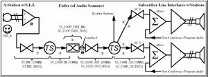
Connection of the Gong Generator to the Gong Timeslot (1) is done at reset time together with the normal tones as described above, while the rest of the Audio Switching for Voice Paging is done dynamically. Connecting and disconnecing the Fader(A Fader Resource is a SBI Channel of an Audio Scanner set in Loopback mode.) via a Timeslot to/from the Audio Program SubChannel (2) of the Subscriber Line Interfaces (2) of the stations in the actual Voice Paging Group are done as the first and last step of a group/all call. The Fader is then used as a common feed point to all members (0…144) of the group for both Gong and Speech, thereby providing click-free switching and improved response times. When connecting the Gong Timeslot to the Fader, the the originator (ASubscriber) is connected in parallel, so she can hear the Gong too (3). In addition to the Audio Switching setup, the Gong Generator is configured and trigged to make the right tones at the right time (4). When the Gong is finished and disconnected, the microphone half of the Subscriber Line Interface for the originating station is connected as shown in the second figure (5) (and disconnected afterwards). In addition to the Audio Switching setup, the station and mic amplifier need to be “Opened” (enabled) to let the audio signal through, and “Closed” again afterwards (7). When in this “speech phase”, the Fader is not faded in and out as part of the connection and disconnection, but is faded in and out by the speech control software (6) depending on the originators use of the M-key and exchange configuration options.
Simplex “Program” Conferences
When the first Subscriber enters the Conference, The Fader (Scanner) is set in Loopback Mode (1) and Connected to the Distribution Timeslot (2) and the Microphone Timeslot (3), without fading in. When the last one disconnects, the opposite actions* is done in the opposite order. When any subscriber enters (leaves) the conference, SubChannel 3 of its Subscriber Line Interface is connected to (disconnected from) the Distribution Timeslot (4). Entering and leaving a conference can be caused by manual (de)activation, automatic (de)activation or temporary masking when the station is busy. The Fader is used as a common feed point to all members of the Conference, thereby providing click-free switching and improved response times. When a subscriber is to start speaking, its speaker is disconnected (5), its microphone is “opened” (6) and connected (7), and the fader faded in (8). When she is to stop speaking, the opposite actions are done in the opposite order. Who, if any, is to speak is determined by M-key use and exchange configuration options (default member++).

