TCAS Connections: Difference between revisions
From Zenitel Wiki
(→Wiring) |
No edit summary |
||
| Line 13: | Line 13: | ||
* By using the plugable screw connector | * By using the plugable screw connector | ||
Connection using the RJ45 connector: | |||
[[File:WiringAnalogTCAS.png|thumb|left|800px]] | [[File:WiringAnalogTCAS.png|thumb|left|800px]] | ||
<br style="clear:both;" /> | <br style="clear:both;" /> | ||
Revision as of 11:48, 31 August 2018
This article describes connection details of the analog intercoms TCAS-1, TCAS-2 and TCAS-3.
Wiring
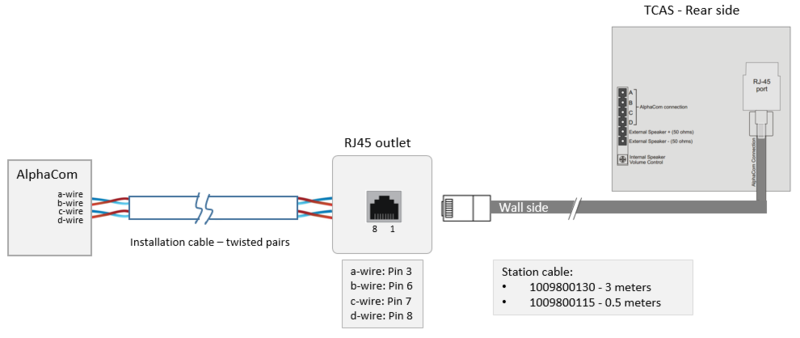
The cabling from the AlphaCom server to the intercom station is star wiring. Two twisted pairs of wires are required. The maximum distance depends on the cable diameter:
- 0.5 mm wires: 1.4 km
- 0.6 mm wires: 2.0 km
- 0.9 mm wires: 4.0 km
The station line can be connected in to ways:
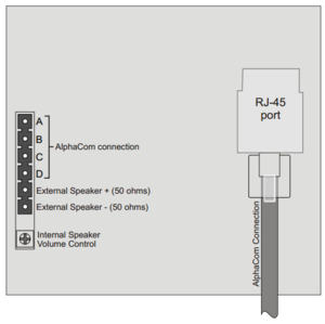
- By means of an RJ45 connector at the rear side of the station, or
- By using the plugable screw connector
Connection using the RJ45 connector:

|
The station cable is not a 1:1 cable! |
For details on connection at the AlphaCom server side, see ASLT - AlphaCom Subscriber Line Board
Second Call Key
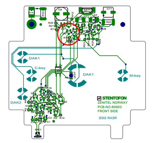
The station is prepared for a future second call key (DAK2).
This second call key can be found on the print if wanted and utilized with an external call button.
- A second external call key must be connected between the A-wire and the lower leg on D6 (highlighted in the image above).


