Difference between revisions of "RIO - Remote Input/Output Unit"
From Zenitel Wiki
| Line 591: | Line 591: | ||
− - NAK / timeout received/sent | − - NAK / timeout received/sent | ||
|} | |} | ||
| + | |||
| + | Even if there is no RCI/RCO activity, the RIO will PING/PONG with the exchange every 40 | ||
| + | seconds causing LED flashes in amber. | ||
| + | |||
| + | The ACK/NAK indication is reset by the next poll of this device, normally after 50 ms times | ||
| + | the number of devices, sometimes later if there is much message traffic. | ||
| + | |||
| + | * During exceptional hardware states: | ||
| + | |||
| + | Non-operational hardware is indicated using flashing between red and green. | ||
| + | |||
| + | {| border="1" | ||
| + | |+ | ||
| + | |bgcolor="silver"|LED Status | ||
| + | |bgcoloer="silver"|Comment | ||
| + | |- | ||
| + | |fast red/green | ||
| + | |Special TEST mode used to activate watchdog | ||
| + | (see description below) | ||
| + | |- | ||
| + | |slow red/green | ||
| + | |Hardware self-test has detected a problem: | ||
| + | - IICB I/O board does not respond, | ||
| + | either due to failure, or the power connector is not in place | ||
| + | |- | ||
| + | |random | ||
| + | red/green/dark | ||
| + | |May occur if the processor does not execute a sensible program, i.e. the | ||
| + | EPROM is dead or missing. On older software without watchdog, electric noise | ||
| + | could make the processor run wild. | ||
| + | |} | ||
| + | |||
| + | |||
| + | |||
| + | |||
| + | |||
| + | |||
Revision as of 13:49, 4 July 2007
Contents
- 1 Features
- 2 Description
- 3 Connectors and Switches
- 4 RS 495 bus
- 5 Installation
- 6 Programming
- 7 Appendix A - Technical Details
- 8 LED Indication
Features
- 8 inputs - programmable to normally open or closed.
- 18 outputs
- Provides connectors for 3 MRBD Multi-Relay Boards with drivers.
- Easy connection in mounting box (included)
- Easy programming of the unit from the AlphaPro programming tool for PC.
- Connects by RS485 or RS232 to the AlphaCom exchange.
- When using RS485, up to 10 units can be chained.
- With RS485 the maximum distance from the exchange is 1 km.
- Status LED on the board.
- Built-in error indication
- Power must be supplied locally if the RIO unit is mounted outside the exchange room.
Description
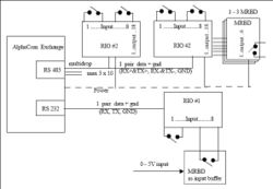
The Remote Input Output Unit (RIO) is a flexible way of connecting digital inputs/outputs to the AlphaCom exchange. The devices can operate on point to point connections (RS 232) or on a multidrop bus (RS 485)
The RIO Unit has two circuit boards - the RIO board and the IICE board (Inter IC Connection Board).
Each RIO unit has 8 inputs and 18 outputs. The outputs are connected to the relayboard MRBD. Each MRBD has 6 relays. If all 18 outputs are used, 3 MRBD boards are required. The RIO and the MRBD are interconnected with a cable included with the MRBD. The RIOs can be mounted away from the exchange room, thus reducing cabling. If response time is critical (<2sec), as in audio control, the internal RCIs and RCOs in the exchange should be used.
The RIO is used for:
- Distribution of remote control outputs (RCOs) from the AlphaCom exchange such as door opening, video camera control, additional call indications etc.
- Connection of technical alarm inputs (RCIs). The alarm inputs can be signals coming from temperature control devices, fire panels, burglar alarms etc. The AlphaCom itself provides 6 RCI (2 in ACM) inputs, this can be increased to 140 RCIs by using the maximum number of RIOs.
Connectors and Switches
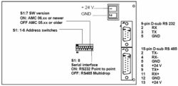
RIO Board
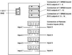
IIEC Board
Serial Interface setting on the RIO Board - Switch S1: 8
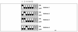
Address setting - Switch S1:1-6
RS 495 bus
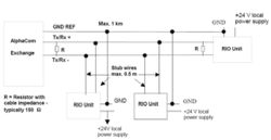
The RS 485 bus can be maximum 1 km long. Up to 10 RIOs can be connected to the bus. The data pair must be terminated in each end with a resistor equal to the cable impedance, typically 150-ohm.
When connecting the RIOs to the bus, wire stubs must be kept as short as possible, preferably less than 0.5 m. All RIOs must be connected to a common GND reference conductor.
NOTE: Use local power supply for each RIO.
NOTE: Do NOT use the GND reference for power distribution.
Installation
General Description
The RIO unit should be installed in a dry and dust free environment. There is easy access to connectors and DIP-switches through openings in the front plate. A 15 pin D-sub with 0,5m of color-coded cable is provided for the RS485 connector. The unit can be mounted to mounting rails.
The RIO unit can be installed in the following locations:
- At the connection field of the exchange.
- Elsewhere in the same room.
- Up to 1km away through the RS485 bus, with 10 units chained together.
- Up to 50 m away through the RS232 bus.
Note: if the RS232 connection is used, surveillance and debugging of the RIO is not possible.
Power supply
The RIO unit can use power from the exchange if it is installed in the exchange room; otherwise it must be powered locally.
Cable requirements
RS485
RIO mounted in the exchange room :
- 2 wires for data.
- 2 wires for power from exchange
RIO mounted outside the exchange room:
- 2 wires for data
- 1 wire for ground reference
- 2 wires for local power.
RS232
- 2 wires for data.
- 1 wire for ground reference
- 2 wires for power from exchange/local power
Installation of the RIO system
Power supply
If local power is used, a regulated 24VDC /1A power supply is necessary.
Note; this is NOT supplied from Stento.
If power from the exchange is used, a Power Distribution Board in the exchange is necessary.
CATION
Do not extend power cables from the PDB outside the exchange rack environment. Use local power for remote installation of equipment.
Installing the RIO Unit
The RIO unit is made up of 2 boards, the RIO board and the IICE board.
- Fasten the RIO unit to a mounting rail.
- Supply both boards with +24V and 0V (GND), each board has its own power connector.
A one-pair ordinary installation cable can be used. (Power cable is not supplied.)
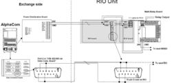
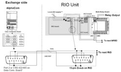
- Connect a cable from one of the exchange's RS485 / RS232 ports to the RIO board. There are 3 possible configurations as shown in Figure 6, Figure 7 and Figure 8:
- A RS485 multidrop bus using power from the exchange, the 0V power connection is also the GND reference for the bus.
- A RS485 multidrop with local power, then a separate GND reference wire is necessary. With the RS485 it is possible to connect up to ten RIO's to the same bus. This is indicated with the continuing bus, the next RIO will be connected the same way as the one shown.
- A RS232 point to point with power from the exchange, with the usual TX, RX and GND signals.
A 15-pin D-sub connector with 0,5m cable is provided for connection to the RS485 bus. Note: a 9-pin D-sub for the RS232 connector is NOT provided.
Installing Multi Relay Board MRBD
If only RIO inputs are used, this board is not necessary. But if RIO outputs are used, MRBD boards must be connected to provide 6, 12 or 18 relay outputs.
- Fasten the Relay Board beside the RIO Unit.
- Supply the board with 24 V and 0 V (GND) from the same power supply as used for the
RIO unit. Use a 1-pair ordinary installation cable for this purpose; the cable is not supplied with the board.
- Connect the RCO output cable between the Relay Board and the RIO.
- On the MRBD-board: Check that the jumpers are in position 2 - 3 on switches S1 to S6.
- Switch the power on.
Installation Examples
Figure 6, Figure 7 and Figure 8 show examples where the MRBD board is installed along with the RIO in order to provide additional RCOs.
Installation of RIO Multidrop with Power from the Exchange
* Port 3 is recommended as this by default is enabled for RIO.
Port 1can also be used but has different pinning.
- Interconnect pin 2 and 11 on Port 1, then connect to RIO pin 9 and 11
- Interconnect pin 4 and 9 on Port 1, then connect to RIO pin 2 and 4.
- * The power connector on the RIO board may not be mounted on older versions of the RIO.
Power is then connected to the 15 pin d-sub on the RIO:
- +24V to pin 6 and 13
- GND to pin 5 and 12
Installation of RIO Multidrop with Local Power
- Port 3 is recommended as this by default is enabled for RIO.
Port 1can also be used but has different pinning.
- Interconnect pin 2 and 11 on Port 1, then connect to RIO pin 9 and 11
- Interconnect pin 4 and 9 on Port 1, then connect to RIO pin 2 and 4.
* * The power connector on the RIO board may not be mounted on older versions of the RIO. Power is then connected to the 15 pin d-sub on the RIO: +24V to pin 6 and 13 GND REF to pin 5
* * * When using local power, the GND of the local power is connected to the exchange GND via the data cable. Make sure that the GND in the local power is floating to prevent ground loop.
Connection of RIO - Point to Point with Power from the Exchange
- * The power connector on the RIO board may not be mounted on older versions of the RIO. Power is then connected to the 15 pin d-sub on the RIO: +24V to pin 6 and 13 GND to pin 5 and 12
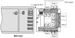
Connection of RCO
Use the cable supplied with the MRBD-board for the 1:1 connection between the RIO Unit and the MRBD-board. Each of the 6 relays has 2 changeover contacts. Relay 1 is controlled by RCO 1; relay 2 by RCO 2 etc.
Connection of RCI
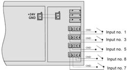
Connect the cable from the external dry contact to the RCI input connectors on the RIO Unit. Keep the cables as short as possible, maximum distance is 3 m. The inputs can be programmed to be normally open or closed.
Programming
General
The AlphaPro programming tool is used for programming of the AlphaCom exchange. If you do not know how to use the AlphaPro programming tool, please consult the AlphaPro User Manual, A100K1005.
- Connect the PC to the exchange.
- Start AlphaPro and select the database for this exchange.
- If you do not have the exchange configuration on your PC already, make a Get All from the exchange (this takes approx. 10 - 15 minutes).
- Do the required programming according to the instructions in this chapter.
- Send information to the exchange (Send All or Send Changed).
- Reset the exchange.
Serial Port Setup
A serial port to be used for the RIO unit must be defined:
- From the AlphaPro main menu, select Exchange & System ➝ Serial Ports.
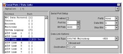
- Select from the list box the serial port to use. You can choose between port 1 to 7 by selecting ACDP Link 1 to 7.
- ACDP Link 1 and 2 can be either RS 232 (point to point) or RS 485 (multidrop)
- ACDP Link 3 is RS 485 (multidrop) only
- ACDP Link 4 – 7 is RS 232 (point to point) only
The Serial Port Setup should be:
- Enabled flag checked
- Bit Rate: 9600
- Parity: None
- Data Bits: 8
- Stop Bits: 1
Data Link Options
When RS 485 is used
- Link Type: ISO1745 Multidrop
- Broadcast: disabled
When RS 232 is used
- Link Type: ISO1745 Point to Point
- Broadcast: disabled
By default port 3 (ACDP Link 3) is enabled for multi-drop (RS 485):
Note: When serial port settings are changed, a reset of the exchange is required after the changes are sent to the exchange.
Define the RIO Unit as a Device
Every RIO Unit connected to the exchange must have a unique device address. The device address is between 1 – 64, and is determined by the DIP-switches S1 1-6 on the RIO unit. Normally you give the first RIO unit address 1, the second one address 2 and so on, but any address between 1 and 64 can be used.
The device address must also be defined in the software.
- From the AlphaPro main menu, select Exchange & System ➝ Devices. The External Devices window is displayed. The list box will show a list of the 64 possible devices.
- Highlight the device number you have chosen for the RIO unit.
- Select device type and serial port to be used. You may also add a descriptive name (optional).
- Device Type: Remote I/O
- Data (ACDP Link): Serial Port 1 to 7
In the External Devices window, the RIO device 1 is defined on serial port 3:
If there are more than one RIO unit, highlight the next device number, and set Device Type
to Remote I/O and select the serial port to be used. Continue until all RIO units are defined.
Define the Remote Control Outputs RCO
Each RIO unit has 18 outputs (RCOs). The outputs must be defined in the software. You only need to define the outputs that are to be used. The address is the device number of the RIO unit. In addition the output number must be defined (1 – 18).
- From the AlphaPro main menu, select Exchange & System ➝ RCO and the Remote Control Output Window is displayed.
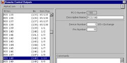
The list box will show a list of the 500 possible RCO’s. By default logical RCO 1 – 138 are assigned to the internal outputs in the AlphaCom exchange (device 65), but can instead be used for the RIO unit. Or you might choose to start defining new outputs from logical RCO 139.
- Select an unused RCO from the listbox, and set the device number identical to the device number of the RIO unit. The pin number must be in the range of 1 to 18. You can also add a Descriptive Name (optional).
In the Remote Control Output Window the logical RCOs 139 – 148 are assigned to RIO device 1, pin number 1 to 10:
Define the Remote Control Inputs RCI
Each RIO unit has 8 inputs (RCIs). The inputs must be defined in the software. You only need to define the inputs that are to be used. The inputs are identified by the device number of the RIO unit and the input number (1 – 8).
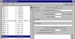
- From the AlphaPro main menu, select Exchange & System ➝ RCI. The Remote Control Inputs window is displayed. The list box will show a list of the 140 possible RCIs. By default logical RCI 1 – 8 are assigned to the internal inputs in the AlphaCom exchange (device 65), but can instead be used for the RIO unit. Or you might choose to start defining new inputs from logical RCI number 9.
- Select an unused RCI from the listbox, and set the device number identical to the device number of the RIO unit. The pin number must be in the range of 1 to 8. You can also add a Descriptive Name (optional). The Remote Control Inputs window below shows logical RCI 9 – 16 are assigned to RIO device 1, pin number 1 to 8:
Assign Functionality to Outputs and Inputs
In general the outputs (RCO) are given the desired functionality in the Event Handler programming in AlphaPro. A wide range of events in the AlphaCom exchange can trigger the RCO.
The inputs (RCI) are given the desired functionality in the RCI programming window. A wide range of commands is available to start actions in the AlphaCom exchange.
Application Example - Door Opening
In this application example the programming for the Door Opening feature is described. During conversation between a Control Room station and a Door Station the Control Room station can press digit 6 to activate an output on the RIO unit. The output activates the door lock.
If the Control Room station is a CRM-IV station, the status of the door (open or closed) can be indicated on an LED in the station. There must be a contact at the door that is connected to the input of the RIO unit.
The example uses:
- Door station number 104 (physical number 4).
- Control room station 112 (physical number 12).
- Logical RCO 139 for door lock.
- Logical RCI 9 for door status indication.
RCO programming
- From the AlphaPro main menu, select Users & Stations.
- Highlight the door station in the list box.
- Go to Events.
- Click + to define a new event.
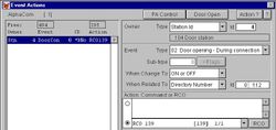
- Select:
| Event Type: | 02 Door Opening – During connection |
| When Change To: | ON or OFF |
| When Related To: | 112 |
| Action Command or RCO: | RCO 139 1/1 |
By this programming only station 112 can activate the door lock. If “When Related To” is set to All, any station in conversation with the door 104 can activate the door lock by pressing digit 6.
The output will be pulsed for 3,5 seconds when the digit 6 is released. The pulse length can be changed in Exchange & System -> System -> RCO Pulse (Door Open) Time.
RCI programming
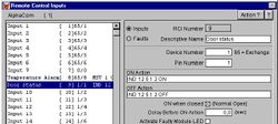
- From the AlphaPro main menu, select Exchange & System → RCI.
- Highlight the relevant RCI in the list box and define the action command.
The IND command is used for indication control in the CRM-IV station.
The action: IND 12 5 1 2 ON means: On physical number 12 - key number 5 - red LED - set flashing – ON.
Appendix A - Technical Details
RIO Cable
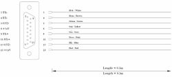
The drawing below shows the color code for the cable included with the RIO Unit.
LED Indication
The RIO unit is equipped with a Light Emitting Diode LED that shows status information. This information is quite useful for troubleshooting. The table below is valid for RIO software 02.10 and later.
- General status for communication, where red is worse, and green best:
| LED Status | Comment |
| fast blinking red | Power on indication and/or no activity on data line.
− After power on reset of RIO. Implies that the software has started and
works OK so far. No communication with the exchange, i.e. data line has
no activity with any device (which happens when there are no devices on,
or the data wires are broken). − After a RESET_DEVICE from the exchange, i.e. device initialization either
due to AlphaCom reset, or AlphaCom PONG time-out (2 minutes, this is
the worst-case time you have to wait if you power-up a RIO while the
exchange is running on AMC older than 07.09 (07.30)). − No polling for more than 15 seconds. I.e. normal operation times out due
to no activity on data line. − After missing multiple PINGs from the exchange (5 min. time-out), indicating AlphaCom device handling high-level problem, or no data line activity (RIO does a software controlled hardware reset) |
| slow blinking red | Some device is being polled, but not this RIO.
− The data connection is electrically OK, but the exchange does not know this device, or there has been bad communication with this device for more than 2 minutes. This situation can last for some 40 seconds, and then the exchange re-tries this RIO again. |
| slow blinking amber | This RIO is being polled by the exchange, but it’s not operational (no RCI/RCO functionality).
− This will occur with AMC versions older than 07.09 (07.30) if the RIO does a quick reset. There is hope, as the exchange will initialize the RIO after max. 2 minutes. |
| slow blinking green | Normal operation mode
− After a GET_DEVICE from the exchange, i.e. finalizing of normal initialization from the AlphaCom - After a PING from the AlphaCom, indicating that the communication works OK high-level. |
- During normal operation:
Indicate message traffic briefly to give an idea about how many messages are sent, and if transmission has problems (orange flashes when green blink).
| LED Status | Comment |
| slow blink amber | Message in queue to be sent to exchange
− Waiting to be polled |
| steady amber | Message is in being transmitted to the exchange
− Select / send /ACK sequence in progress. |
| steady green | Message received successfully
− ACK received |
| steady red | Message not received/sent successfully
− - NAK / timeout received/sent |
Even if there is no RCI/RCO activity, the RIO will PING/PONG with the exchange every 40 seconds causing LED flashes in amber.
The ACK/NAK indication is reset by the next poll of this device, normally after 50 ms times the number of devices, sometimes later if there is much message traffic.
- During exceptional hardware states:
Non-operational hardware is indicated using flashing between red and green.
| LED Status | Comment |
| fast red/green | Special TEST mode used to activate watchdog
(see description below) |
| slow red/green | Hardware self-test has detected a problem:
- IICB I/O board does not respond, either due to failure, or the power connector is not in place |
| random
red/green/dark |
May occur if the processor does not execute a sensible program, i.e. the
EPROM is dead or missing. On older software without watchdog, electric noise could make the processor run wild. |


