TCIx Connections
From Zenitel Wiki
This article describers all Turbine Compact IP Standard Station connections.
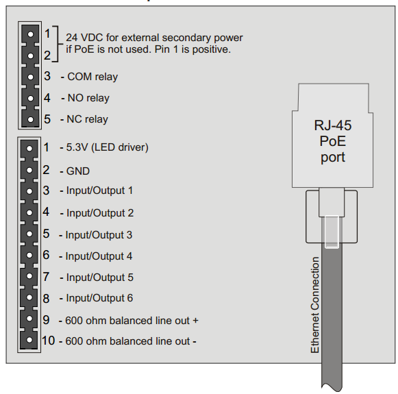
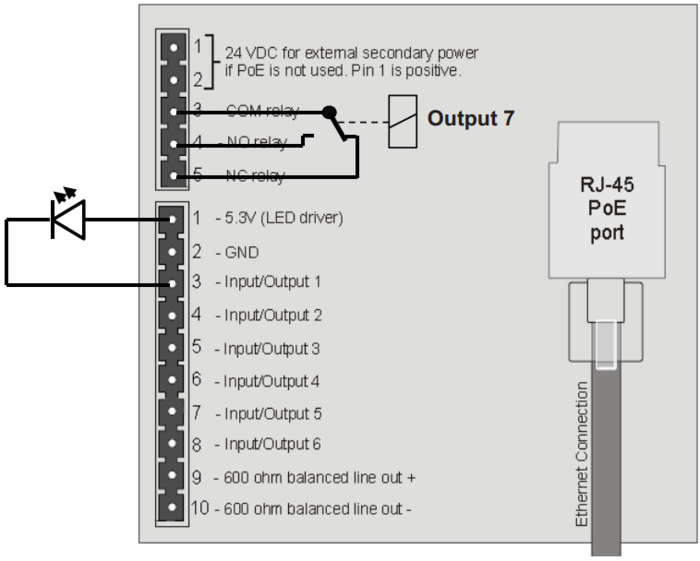
The Turbine Compact IP station has a RJ-45 PoE/LAN port, and 6-pin & 10-pin external connectors.
| Ethernet/Power | 10/100 Mbps Ethernet RJ-45 port for LAN (uplink) connection. Supports PoE (802.3af). Draws power from either spare line or signal line. |
| Secondary Power | 24 VDC (16 – 48 V) secondary power is provided from an external adapter. |
| Relays | There is one Double Throw relay contact with 60W switching power. COM, NO, NC contacts are provided. Max: 250VAC/220VDC, 2A, 60W. |
| Input/Output | 6 I/Os are available. Each I/O can be configured as either input, output, or LED driver. |
| Audio Line Out | A balanced 600 ohm audio line out with induction loop signal |
Note! Use cables crimped with ferrules for terminal block connectors
- When the Turbine Station is connected to the network, its IP address is automatically obtained from a DHCP server or an IP address in the range 169.254.x.x will be assigned.
- To make the station speak its IP address, press the call button on the station.
PCB - Front
P1 RJ45 PoE port for 10/100 Mbit Ethernet connection.
- The station can be powered from this port if the line supports Power over Ethernet (PoE).
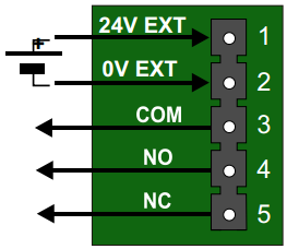
P26-pin plug-on terminal for external connections.
- Pin 1/2 24 VDC for external secondary power if PoE is not used. Pin 1 is positive.
- Pin 3 COM relay
- Pin 4 NO relay
- Pin 5 NC relay
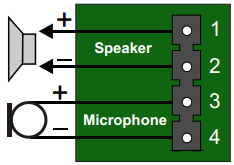
P4 Loudspeaker & Electret microphone
- Pin 1 10W Speaker amplifier +
- Pin 2 10W Speaker amplifier -
- Pin 3 Electret Microphone +
- Pin 4 Electret Microphone -
Input Connectors
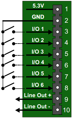
P3 10-pin plug-on terminal for external connections.
- Pin 1 5.3V
- Pin 2 GND
- Pin 3 Button Input or LED Driver
- Pin 4 Button Input or LED Driver
- Pin 5 Button Input or LED Driver
- Pin 6 Button Input or LED Driver
- Pin 7 Button Input or LED Driver
- Pin 8 Button Input or LED Driver
- Pin 9 600 ohm balanced line out +
- Pin 10 600 ohm balanced line out -1
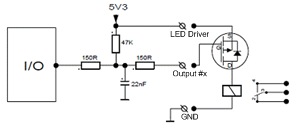
Output Connectors + 1 relay
The extra relay for any of the 6 I/O pins is connected as shown:
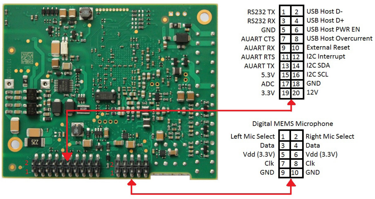
PCB - Rear
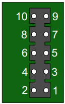
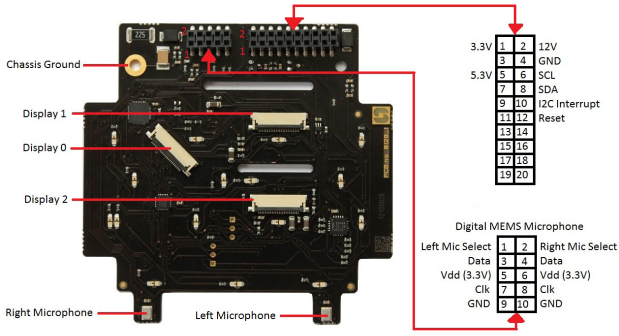
J6 10-pin terminal for digital MEMS Microphone
- Pin 1 Left mic select (Vdd)
- Pin 2 Right mic select (GND)
- Pin 3 Data
- Pin 4 Data
- Pin 5 Vdd 3.3V
- Pin 6 Vdd 3.3V
- Pin 7 CLK
- Pin 8 CLK
- Pin 9 GND
- Pin 10 GND
Front Board - Front
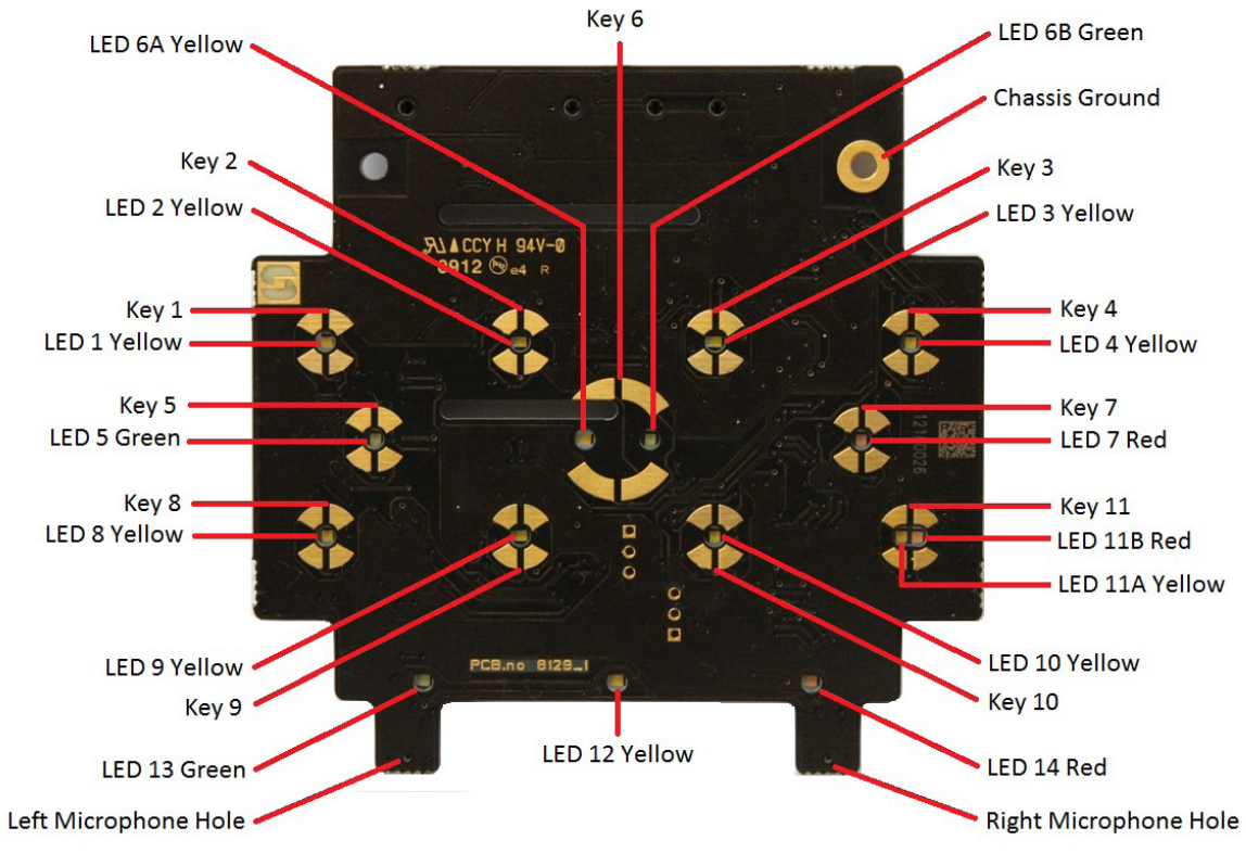
Front Board - Rear

