IP Heavy Duty Connections
From Zenitel Wiki
Introduction
The table below is an overview of the main connectors involved when installing the STENTOFON IP Heavy Duty stations.
Note! To access these connectors the frontplate must be removed
| LAN | 10/100 Mbps RJ-45 port for LAN (uplink) connection. Supports PoE (802.3af). Draws power from either spare line or signal line. |
| AUX | 10/100 Mbps RJ-45 ports for auxiliary equipment such as PC and IP camera. |
| Input/Output | Pluggable screw terminal |
| Local Power | Plugable screw terminal, 19-27 VDC Idle 4W, max. 8W |
Power Supply
The IP Heavy Duty Station supports Power over Ethernet (PoE, IEEE 802.3 a-f) where power can be drawn from either the spare line or signal line.
If PoE is not available, the IP Substation can be connected to a 24 VDC local power supply.
Network Connection
There are two RJ45 ports on the IP Heavy Duty stations:
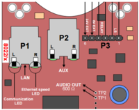
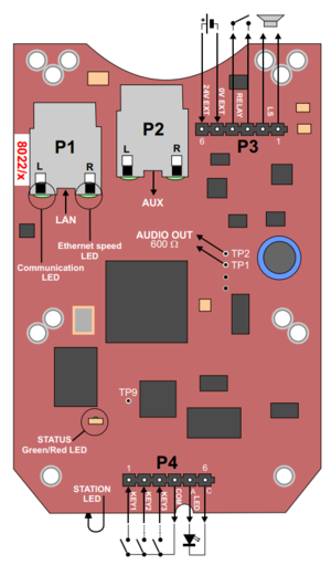
- LAN port (P1): for connecting to the network and the AlphaCom XE Audio Server.
- AUX port (P2): for connecting to auxiliary equipment such as a PC or IP Camera.
Input/Output Connections
There are I/O connection options for all IP Substations. These I/O connections include:
- 3 digital inputs (P4):
- Input 1 = PTT from headset, and for restoring factory default
- Input 2 = Call button no.2 or logical input (optional)
- Input 3 = Hookswitch
- 1 relay output (P3)
- 1 logical output (TP9)
- 1 Line out (TP1/2): Audio output to handset speaker (0dBm 600ohm balanced)
For more details see INCA Substation Board Connectors.


