AE1 - AlphaCom Digital Network Board
From Zenitel Wiki
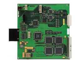
The AE1 board provides AlphaCom with two E1 or T1 telecom interfaces. The AE1 board in an integrated board which fits into the AlphaCom back plane. The AE1 board converts between the internal SigmaDelta audio format and G.722 or G.711 PCM. The AE1 board also has 7 RS232 ports, which can be transported in E1/T1 channels using a proprietary adaptation protocol. Finally the AE1 board can be configured to do transparent switching of timeslots between the two E1 links. The switching pattern is static only, must be configured using a terminal monitor.
Highlights
- AlphaNet and multi-module links
- 2.048 and 1.536 Mbit links according to the E1/T1 standards
- Built-in multiplexer
- Direct connection to the AlphaCom audio busses
- Direct back-to-back connection up to 1 km distance; for larger distances, connection through approved transmission equipment is required
Additional Documentation
For more documentation please see http://www.zenitel.com/product/product/ae1-digital-network-card
Description
Exchange support
The AlphaCom and AlphaCom 80+ exchanges have support for the AE1-cards as follows:
- AlphaNet connectivity: Slots 22 and 23
- Multi-module linking: Slots 22, 23 and 24
The AlphaCom M supports the AE1-card as follows:
- AlphaNet connectivity: Slots 4 and 5
- Multi-module linking: Slots 4, 5 and 6
Towards the backplane of the exchange, the AE1-card interfaces to 32 bi-directional Sigma-Delta audio channels.
When used for AlphaNet connectivity, the AE1-card must be located in the master module (device 65); for multi-module use, an AE1 card must be present in each module. AE1 Installation and Commissioning Manual A100K10292/1.0 7
E1 and T1 description
E1/T1 are point-to-point, synchronous links.
- E1 has a speed of 2.048 Mbit/sec, which is divided into 32 timeslots of 64 kbit/sec each. Timeslot 0 is reserved for synchronisation, which means that 31 time slots are available for transmission of information. E1 has a 4-wire balanced interface (separate pairs for transmit and receive), with a 120 Ohm impedance.
- There is also a specification for a 75 Ohm unbalanced interface. The AE1-card does not support this interface, but 3rd-party equipment exists for matching between these 2 different interface specifications.
- The AE1-card can be set into a non-standard E1Cat5 mode, for use with 100 Ohm CAT5 cabling.
- T1 has a nominal speed of 1.536 Mbit/sec, which is divided into 24 timeslots of 64 kbit/sec each. In T1 there is no reserved timeslot for synchronisation; synchronisation is achieved by the addition of 1 bit to each 192-bit frame. This makes the real speed of the link 1.544 Mbit/sec. T1 has a 4-wire balanced interface (separate pairs for transmit and receive), with a 100 Ohm impedance.
Installation
The AE1-card is intended to be used for AlphaNet and multi-module linking of exchanges. The card can be used both for the audio and data transfer. The audio is taken directly from the backplane of the exchange. The data links are the same as normally used for data connections between exchanges and are to the serial ports available at the back of an exchanges, either on the Serial Port Connection Board (SPCB) in AlphaCom and AlphaCom 80+ exchanges, or directly on the backplane of the AlphaCom M. These serial ports need to be linked to serial ports on the AE1-card itself, after which the data can be transported over the E1/T1 links.
APC
The APC (in AlphaCom and AlphaCom 80+ exchanges) generates the clock signals for all cards inside the exchange. When an AE1-card is present, this clock will be synchronised to a clock signal on the AE1-card. On the APC, this synchronisation is only possible if the potentiometer related to the clock frequency is not in an extreme position (totally clockwise or anti-clockwise). In case of doubt, put the related potentiometer in the middle position.
Details on synchronisation in the AlphaCom M exchange
AlphaCom and AlphaCom 80+
In the AlphaCom and AlphaCom 80+ exchanges, AE1-cards can be placed in the following card position:
- Positions 22 and 23 for use in AlphaNet configuration. Cards for this use can only be placed in the master module of a multi-module exchange.
- Positions 22, 23 and 24 for use in multi-module linking. In this case AE1-cards must be present in the same card positions in all modules to be linked. Normally only card position 24 will be used for this purpose.
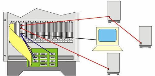
For the AlphaCom and AlphaCom 80+ there is a special filter card FBE1 with ordernr 1009509000. This card has a micro ribbon connector and 2 RJ45 connectors. The RJ45 connectors are industry standard 4-wire connection points for the E1/T1 interfaces. The micro ribbon connector gives access to all serial ports on the AE1-card.
The filter card is delivered with an ‘Octopus’-cable on which the console and 3 general purpose serial ports are terminated. One of these connectors is female and can be connected directly (or via a 1-to-1 serial cable, such as the cable for AlphaPro) to the 9-way serial port of a PC. The other 3 connectors are male and can be plugged directly into RS232 serial ports on the SPCB. These 3 connectors are labelled SP #1, SP #2 and SP #3, which refer to these three serial ports on the AE1-card. If more serial port connections are required to the AE1-card, a custom cable must be made.
Connections
The connections on the RJ45 connectors follows the industry standard for E1/T1 and is the same on both connectors:
- Tx+: 4
- Tx-: 5
- Rx+: 1
- Rx-: 2
- GND: 3, 6 and shield (normally this GND connection is not made, as E1/T1 is a 4-wire link and UTP cable can be used for E1 and T1 connections; these GND points are the same and connected together on the FBE1-card itself)
The pin assignment on the female console connector SP C is:
- Tx: 2
- Rx: 3
- Gnd: 5
The pin assignment on the 3 male serial port connectors SP #1, SP #2, SP #3 is:
- Tx: 3
- Rx: 2
- Gnd: 5
The pin assignment of the micro ribbon connector on the filter card is:
| Tx | Rx | Gnd | |
| SP C | 2 | 1 | 20 |
| SP #1 | 4 | 3 | 22 |
| SP #2 | 6 | 5 | 24 |
| SP #3 | 8 | 7 | 26 |
| SP #4 | 10 | 9 | 28 |
| SP #5 | 12 | 11 | 30 |
| SP #6 | 14 | 13 | 32 |
| SP #7 | 16 | 15 | 34 |
E1/T1 cable
For direct back-to-back connections between AE1-cards a crossed cable terminated at both ends with 8-pole RJ45 connectors is required. The interconnections between the connectors is as follows:
- Rx+: 1 ↔ Tx+: 4
- Rx-: 2 ↔ Tx-: 5
- Tx+: 4 ↔ Rx+: 1
- Tx-: 5 ↔ Rx-: 2
Note: There are circumstances that a straight cable is required. This is when the cable plugging into the exchange is only a section of the total wiring between exchanges. In this case there should only be one section which is crossed. Note: An E1/T1 cable is not the same as a 10base-T Ethernet cable. Such an Ethernet cable uses different poles in the RJ45 connector.
AlphaCom M
In the AlphaCom M exchange, AE1-cards can be placed in the following card position:
- Positions 4 and 5 for use in AlphaNet configuration. Cards for this use can only be placed in the master module of a multi-module exchange.
- Positions 4, 5 and 6 for use in multi-module linking. In this case AE1-cards must be present in the same card positions in all modules to be linked. Normally only card position 6 will be used for this purpose.
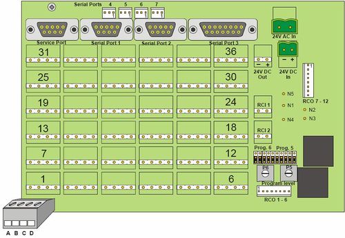
The AlphaCom M screw terminal field provides access to both E1/T1 interfaces and the serial ports.
The AE1-card can only be used with AlphaCom M exchanges with backplane version 2.00. This backplane supports AE1-card related filtering and clock synchronisation. In addition, this backplane version features an additional RCO connector related to ASLT card position 2 (6 extra RCO’s), as well as 4 more RS232 serial ports (AMC serial ports 4, 5, 6 and 7).
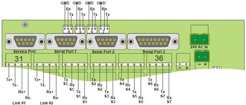
On these additional serial ports, the pin assignment is (see also Figure 4):
- Tx: pin 1
- Rx: pin 2
- GND: pin 3
Connections
Connections are made to the screw terminals related to the position in which the AE1-card is situated (position 4, 5 or 6; connectors 19-24, 25-30 or 31-36).
- E1/T1 link #1: Tx+: a19 (25, 31), Tx-: b19 (25, 31), Rx+: c19 (25, 31), Rx-: d19 (25, 31)
- E1/T1 link #2: Tx+: a20 (26, 32), Tx-: b20 (26, 32), Rx+: c20 (26, 32), Rx-: d20 (26, 32)
- Console RS232 serial port, SP C: Tx: a21 (27, 33), Rx: b21 (27, 33)
- Serial Port #1, SP #1: Tx: c21 (27, 33), Rx: d21 (27, 33)
- Serial Port #2, SP #2: Tx: a22 (28, 34), Rx: b22 (28, 34)
- Serial Port #3, SP #3: Tx: c22 (28, 34), Rx: d22 (28, 34)
- Serial Port #4, SP #4: Tx: a23 (29, 35), Rx: b23 (29, 35)
- Serial Port #5, SP #5: Tx: c23 (29, 35), Rx: d23 (29, 35)
- Serial Port #6, SP #6: Tx: a24 (30, 36), Rx: b24 (30, 36)
- Serial Port #7, SP #7: Tx: c24 (30, 36), Rx: d24 (30, 36)
- For GND return for external equipment connected to the serial ports, use the ’-‘ connection of the 24V DC OUT screw terminal.
Wiring examples
The wiring required at the AlphaCom M is best illustrated by an example:
- AlphaCom M node 1 with an AE1-card in card slot 4
- AlphaCom M node 2 with an AE1-card in card slot 5
- AlphaNet connection between the nodes, using line interface #1 at node 1 and line interface #2 at node 2
- At node 1, AMC serial port 1 is used for the AlphaNet data link
- At node 2, AMC serial port 4 is used for the AlphaNet data link
- At both nodes, AE1-card serial port 1 is used for the AlphaNet data link
The following connections are needed:
- The E1/T1 link:
- Node 1: connector 19 ‘a’ (Tx+) Node 2: connector 26 ‘c’ (Rx+)
- Node 1: connector 19 ‘b’ (Tx-) Node 2: connector 26 ‘d’ (Rx-)
- Node 1: connector 19 ‘c’ (Rx+) Node 2: connector 26 ‘a’ (Tx+)
- Node 1: connector 19 ‘d’ (Rx-) Node 2: connector 26 ‘b’ (Tx-)
- Serial data connection at Node 1:
- Connector 21 ‘a’ (Tx) AMC serial port 1 pin 3 (Rx)
- Connector 21 ‘b’ (Rx) AMC serial port 1 pin 2 (Tx)
- Serial data connection at Node 2:
- Connector 27 ‘a’ (Tx) AMC serial port 4 pin 2 (Rx)
- Connector 27 ‘b’ (Rx) AMC serial port 4 pin 1 (Tx)
AlphaCom M: Upgrade of already installed exchanges
AlphaCom M exchanges delivered prior to or around the time of the first release of the AE1-card (September 2003) cannot be used with the AE1-card, due to the fact that the previous version of the AlphaCom M backplane has no support for this card.
The AlphaCom M backplane has been upgraded to provide the possibility of clock synchronisation, without which the AE1-card will not work.
It is possible to upgrade an existing system by replacing the backplane with a new version. The order number for a new backplane is: A100C07815.0200.
The procedure for changing the backplane is as follows:
- Switch off the power.
- Remove all cards from the exchange, including the power module.
- Remove all connections to the backplane.
- Loosen the fastening of the backplane and remove the backplane.
- Place the new backplane on the back of the exchange and fasten. Do not fasten the screws too tightly at this stage.
- Carefully place some of the cards back into the exchange, making certain that the cards mate with the backplane connectors correctly. As the backplane should not be fastened tightly yet, it is possible to align backplane and cards correctly.
- Tighten the backplane screws.
- Replace all cards and the power module, if they are not in the exchange yet.
- Re-connect all cabling.
- Switch-on the power.
An easy way to see the difference between the previous and new version of the backplane, is the fact that the new backplane has an additional connector for RCO’s (2 instead of 1), and connectors for 4 additional serial ports.
AlphaNet
AlphaNet requires audio and data links between exchanges.
The audio connections are directly made on the backplane of the exchange. This does not require any special installation.
For the data connections, the AE1-card provides 7 general purpose RS232 serial ports. Data on these ports can be routed on any available E1/T1 time slot. These serial ports can be used for the data links between exchanges by wiring such a port to the required port on the Serial Port Connection Board (SPCB), which is a standard item in an AlphaCom or AlphaCom 80+ exchange.
Ports 1, 2, 4, 5, 6 and 7 on this SPCB provide RS232 interfaces. In an AlphaCom M, the serial ports connectors on the backplane (port1 and port 2) can be used directly. Only 2 wires, Tx and Rx need to be connected, as the GND return path is provided inside the exchange. On the SPCB and the AlphaCom M backplane connectors, Tx is pin 2, Rx is pin 3. In both cases, the serial ports are actually on the AMC-card inside the exchange.
As a standard the ‘Octopus’-cable has 3 serial port connection cables.
Multi-module
A multi-module configuration requires audio rings and data links between the different modules. In E1-mode the AE1-card can provide a maximum of 31 audio rings between modules. This is the case if the E1 connection is only used for the audio rings and the data connections are directly between the SPCB’s of the different modules.
In case that also the data is routed via the E1-links, 30 or 29 audio rings can be provided, depending on the number of modules to be linked. In this case the appropriate AE1-serial ports are connected to the SPCB in the same module.
There is a pre-programmed configuration for the AE1-card, which requires the following connections between the modules:
- E1 link #2 module 65 <--> E1 link #1 module 66 (required for 2 modules)
- E1 link #2 module 66 <--> E1 link #1 module 67 (required in addition for 3 modules)
- E1 link #2 module 67 <--> E1 link #1 module 68 (required in addition for 4 modules)
The pre-programmed configurations for the AE1-card where data is also routed via the E1/T1 link(s) require the following connections between the serial ports:
| Module
65 |
AMC port2<-
→ AE1port3 |
|||
| Module 66
AMC port0<- →AE1 port1 |
AMC port1<-
→AE1 port2 |
AMC port2<-
→AE1 port3 | ||
| Module
67 |
AMC port0<- | →AE1 port1 | ||
| Module 68 | AMC port0<- | →AE1 port1 |
Serial ports, other uses
The serial ports on the AE1-card are for general purpose use. Any equipment with an RS232 serial data port can be connected to the card, and the serial data can then be transferred across the E1/T1 link. The serial ports support 9600 and 38400 baud as data rate, with 8 data bits, 1 stop bit and no parity.
Status indicators
The AE1-card has 5 leds on the front, giving an indication of the status of the card and the lines. The top led indicates the card status, the other leds are related to the line interfaces.
Card-status indicator
The card status indicator is a multi-colour led:
- Green light - Board is OK and ready for use
- Green blinking light - Board is OK, some of its local audio channels are in use
- Yellow light - Board is initialising
- Red light - Board has reset signal set, or the board is malfunctioning
- No light - Board has no power or no system clock
- Blinking pattern, Dark - red - green - yellow, each cycle is one second: AE1 is in Boot Loader Mode
- Blinking pattern, Green (1.7s) - red (0.3s): Error, APC fails to synchronise to enabled reference clock (refck), see Synchronisation
- More than one AE1 in the same card cage with active reference clock (refck)
- Calibration potentiometer on APC or AC M maybe in an extreme position, set to middle
- APC or AC M backplane may need servicing
Line interface indicator
There are 2 status leds for each line, which makes 4 in total:
- The top 2 line status leds are for E1/T1 line #1
- The bottom line status leds are for line #2
The top led of each pair is red, the other led is green.
- Green light - Link is OK
- Red light - Link is malfunctioning, signal cannot be decoded at all
- Missing signal, or wrong configuration, for instance one end of the link is set to E1 while the other end is set to T1
- Green and Red both steady - Basic decoding of signal works
- Probably wrong configuration of link, e.g. doubleframe vs. multiframe
- Remote alarm received from peer end, which will happen if the communication works in one direction (if the connection is directly to another AE1-card, the indication at the peer end will be red)
- Green steady, irregular flickering of Red - Basic decoding of signal works
- Probably bad signal quality due to noise or an incorrect signal level
- Green steady, steady blinking of Red - Basic decoding of signal works
- Frame slips on received data due to different speed of data, one blink for each frame slip
- Incorrect configuration (‘refck’ command)
- APC refck synchronisation does not work (less likely, and this will also be indicated on Board Status led)
The above means that the red led of an unused interface will always be on.
Quick test of the E1/T1 links
It is possible to connect the 2 E1/T1 interfaces on the same board back-to-back. When they communicate correctly, for both interfaces the green led will be on, and the red led will be off. No special programming is required for this test, other then to make certain that both interfaces are set to the same settings, see AE1-card programming. This can be used to do a test on the interfaces themselves if there is any difficulty in connecting to either external equipment or an AE1-card in another exchange or module.
Note that it can take up to 30 seconds for an E1/T1 link to synchronise. This is normal. During this time the red leds will be on.
Line length
The default settings in the ‘tli mode’ command and the optional parameters given in E1/T1 interface modes support a line length of 1 kilometre in ‘longhaul’ mode, depending on the cable used. The cable specifications are:
- E1 mode: 120 Ohm/24AWG (0.5mm)
- T1 mode: 100 Ohm/24AWG (0.5mm)
- E1Cat5 mode: CAT5 cable, which is 100 Ohm/24AWG (0.5mm)
- T1 mode: used with CAT5 cable
In case of difficulties of linking exchanges back-to-back using the appropriate cable and adhering to the maximum cable length, please contact our customer support department.
Note: The AE1-card and filter board have insufficient protection against lightning. The cable should not run outside buildings. The card is not tested against specification K.41.
Third party equiment
The AE1-card is intended both for back-to-back connection and connection to third party equipment. Third party equipment can for instance be an ATM-network on which a full or fractional E1/T1 link can be transported, if need be worldwide. In fact any network which provides an E1 or T1 connection point can be utilised to link AlphaNet nodes or modules in multi module exchanges.
The maximum E1/T1 line length is 1 km. In case that AE1-cards need to be linked together across larger distances, and a transport network is not available, the card can be connected to HDSL, fibre optic or other modems with an E1 or T1 interface. The distance that can be bridged with such equipment depends on a number of factors. However a distance of 80 km can be reached without repeaters using high quality mono-mode optical fibres and an appropriate light source wavelength. Note the following points:
- Any echo cancellation in the equipment/network should be turned off
- Serial data timeslots need to be transparent since the protocol used between nodes or modules is proprietary
- Bandwidth compression of audio timeslots is OK as long as the sound level dynamics of the sound is not impaired too much (it is impossible to quantify this statement, and this kind of compression is not recommended)
Programming
Programming of an AlphaCom system with AE1-cards requires programming both of the AE1-card(s) and AlphaPro.
AE1-card programming
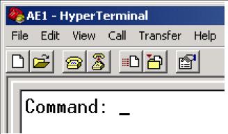
The card can operate in different modes. In addition, multiplexing between the different sources/destinations must be set up. For this a number of commands are available, which can be entered in ASCII format. Connect a terminal, or PC running for instance the Microsoft ‘HyperTerminal’ program, to the console serial port. The settings are 8 data bits, 1 stop bit, no parity, 9600 baud, with Xon/Xoff flow control. The command interpreter is always active. If the command prompt is not visible on the screen, just press the ‘Enter’-key once, or reset the AE1-card.
Important note: After reset the AE1-card always uses the configuration as stored in its flash-memory. The only way of writing to that memory is by using the save’-command.
Synchronisation
An important point for proper operation is the synchronisation of the links. An E1/T1 link is a synchronous link. Timing between the different links is very important. All synchronisation of all links in a complete system must be able to be traced back to the same source.
In case that an AE1-card is connected to an external network, it will normally be the network which provides the synchronisation, as such networks normally have other equipment connected to them as well. It is not acceptable that connected equipment forces its synchronisation on to the network, and any other equipment connected to it. Normally a network provides a very stable and accurate clock signal.
In the AlphaCom exchange and the AE1-card, synchronisation works as follows:
- In the receive direction, synchronisation is always to the received data.
- The received data is clocked in on a clock regenerated from this received data itself. This means that if the data is sent from a network with an accurate clock, the regenerated clock is just as accurate.
- In the transmit direction, transmission is always synchronised to the APC clock, which itself is synchronised to another source.
- If there are a number of AE1 cards in the exchange, all links have therefore exactly the same transmit timing
- The AE1-card can provide the synchronisation for the APC clock.
- When the AE1-card is connected to external equipment with a stable and accurate clock, the regenerated receive clock should be used to also synchronise the APC clock. In that case the transmitted signal from the AE1-card will be just as accurate and stable as the network clock and the signal can then be connected to that network without experiencing loss of data and audio noise due to bad synchronisation.
The command to set the APC-clock synchronisation is refck; the format, with parameters, is as follows:
- refck tl1 – uses the clock signal derived from received data on E1/T1 interface #1
- refck tl2 – uses the clock signal derived from received data on E1/T1 interface #2
- refck master – if there is no stable clock from an external source available, the AE1-card has an accurate crystal which can be used to synchronise the APC clock (use this when for instance 2 exchanges are connected back-to-back)
- refck off – if there are multiple AE1-cards present in a module, only 1 of the cards should provide the synchronisation towards the APC clock, the other AE1-cards must have this possibility turned off; refck off is the default setting
Example: When 2 exchanges are connected back-to-back in an AlphaNet configuration and there is a direct connection between the AE1-cards, use the command refck master for the AE1-card in one of the exchanges, while the command refck tl1 is used for the card in the other exchange (assuming that the card is linked via interface #1). The exchange with the card in master mode will provide an accurate clock in the transmit direction. The other exchange will be synchronised to this same stable clock, and therefore will use this same clock for its transmissions. In effect, the APC-clocks of the 2 exchanges will have the exact same timing.
There is one additional parameter, which is status. This can be used if the status leds give an indication that something is not correct, see Status indicators.
- refck status – a message will be displayed with information about which of the possible sources that the AE1-card has is actually synchronising the APC-card and whether this synchronisation is working correctly
E1/T1 interface modes
The command to set the mode of the E1/T1 interfaces is tli mode (sets the mode of both interfaces to the same), tli 1 mode (sets the mode of interface #1) or tli 2 mode (sets the mode of interface #2).
The first parameter behind the command sets the mode, and can be:
- e1
- t1
- e1cat5 – E1 is a 4-wire connection with a 120 Ohm impedance. When the interface is in e1cat5 mode, the impedance is set to 100 Ohm, which matches the impedance of Cat5 cabling.
Additional parameters are normally not required. The default settings and options for E1 are:
- HDB3 coding
- multiframe (CRC4 multiframe)
- shorthaul (maximum distance 200 m)
- E1 optional parameters
- doubleframe (alternative framing)
- autoframe (accepts both multiframe and doubleframe; this should be used if the framing is likely to be changed often, but it will affect the line status monitoring)
- longhaul (use for distances up to 1 km)
- tlpb (when an external heavy duty trunk line protection card is used)
The default settings and options for T1 are:
- B8ZS coding
- ESF, with alternative names F24 and CRC6
- shorthaul (maximum distance 200 m)
- T1 optional parameters
- F4 (alternative framing)
- F72, with alternative name SLC96 (alternative framing)
- F12, with alternative names D4 and D3 (alternative framing)
- longhaul (use for distances up to 1 km)
- tlpb (when an external heavy duty trunk line protection card is used)
Normally the mode of both interfaces on an AE1-card will be the same, in which case the tli mode command can be used. It is however possible that one of the interfaces is connected to an E1-network, while the other interface (for instance #2) is directly connected to the AE1-card in another exchange via CAT5 cabling. In that case the following commands will set the mode correctly for such use:
- tli 1 mode e1
- tli 2 mode e1cat5
Multiplexing
The AE1-card has built-in multiplexer capabilities. This means that audio and data from the AlphaCom exchange can be assigned to any available E1/T1 timeslot. It is also possible to multiplex timeslots between the two E1/T1 interfaces.
The possible sources and destinations on the AE1-card are as follows:
- There are 7 general purpose serial ports, referred to as S1-S7
- E1 link #1 has 31 accessible timeslots, referred to as A1-A31 (A1-A24 in T1 mode)
- E1 link #2 has 31 accessible timeslots, referred to as B1-B31 (B1-B24 in T1 mode)
- There is access to 32 audio timeslots on the backplane (L1-L32)
Connections between the following sources/destinations are allowed:
- Link1 ↔ Link2
- Link1 ↔ Backplane audio
- Link2 ↔ Backplane audio
- Link1 ↔ Serial ports
- Link2 ↔ Serial ports
The command to be used is switch. Both bi-directional as uni-directional switch commands are allowed, where uni-directional switch-commands are generally only used in multi-module configurations. Some examples are (note that the use of a space character ‘ ’ in front of and behind the operators <, > and <> is mandatory):
switch A1 <> L1 – put the contents of backplane audio interface L1 into the first timeslot of E1/T1 interface #1 AND put the contents of the first timeslot of E1/T1 interface #1 into the backplane audio interface L1
- switch A3 > B7 – put the contents of the 3rd timeslot of E1/T1 interface #1 into the 7th timeslot of E1/T1 interface #2
- switch B7 < A3 – this command has the same effect as the command above
When connecting to other multiplexers care must be taken not to use timeslots which are already in use on the link (for instance, in E1 links, time-slot 16 is very often used for D-channel data links).
Pattern commands
As the AE1-card is intended to be used in AlphaNet and multi-module configurations, there are some pre-defined set-ups which can be used. The command for this is pattern with a parameter. The effect of using the ‘pattern’ command with a parameter is that multiple ‘switch’-commands are pre-loaded.
For multi-module configurations the parameters are:
| Serial data | Module # | 2 modules | 3 modules | 4 modules |
| On E1/T1 links | 65 | master | master | master |
| On E1/T1 links | 66 | slave-last | Slavel-3mod | slavel-4mod |
| On E1/T1 links | 67 | Slave-last | slave2-4mod | |
| On E1/T1 links | 68 | slave-last | ||
| Separate | 65 | master-
nodata |
master-
nodata |
master-
nodata |
| Separate | 66 | slave-
last- |
slave-
middle- |
slave-
middle- |
| Separate | 67 | Slave-
last- |
slave-
middle- | |
| Separate | 68 | slave-last-
nodata |
The hardware multi-module configuration as described in paragraph 3.5 is based on the use of this command. If the data connections are made directly between modules, the E1-links can carry 31 audio rings. If the data is routed across the E1-links, 1 or 2 timeslots are used for these data links, so 30 or 29 audio rings can be provided. In all cases, a T1 configuration will carry 7 audio rings less. The configurations which route data across the links use timeslot 24 (and 23 in case of 4 modules) for the transport of the data. In this way the pattern parameters are usable for both E1 and T1 configurations.
For AlphaNet there are the following pattern parameters:
- leaf (or leaf-2s) – default pattern to be used in most cases in 2-exchange AlphaNets and for ‘leaf node’ exchanges in bigger AlphaNets (i.e. exchanges in the periphery of the network that are connected with a single E1/T1 line to the rest of the network); 2 serial data connections are provided; the second serial data connection can either be used for a second AlphaNet data link if needed, be left unused or be used for remote access to the AE1 console port, to non-AlphaNet AMC ports or to serial ports on external equipment. The audio links are connected A1-A22 <> L1-L22 and A25-A31 <> L25-L31 while serial ports are connected as follows: A24 <> S1 and A23 <> S2. L23 and L24 are left unconnected.
- leaf-nodata – alternative to ‘leaf’ when the maximum possible number (31) of audio channels are needed, and the AlphaNet data connections are separate from the E1/T1 line. The audio links are connected A1-A31 <> L1-L31.
- leaf-1s – alternative to ‘leaf’ when the maximum possible number of audio channels (30) are needed, but a single serial data connection is required on the E1-link. The audio links are connected A1-A23 <> L1-L23 and A25-A31 <> L25-L31 while the serial port is connected A24 <> S1. This configuration can for instance be used for 2 AlphaComs connected back-to-back in a 2-node AlphaNet configuration.
- leaf-3s – alternative to 'leaf' when a third serial data connection is needed. The following audio links are connected: A1-A21 <> L1-L21 and A25-A31 <> L25-L31 while serial ports A24 <> S1, A23 <> S2 and A22 <> S3 are connected. L22-L24 are unused.
- dual-line – 16 audio and 2 data channels on each line interface (A1-A16 <> L1-L16, B1-B16 <> L17-L32, S1 and S3 <> A24-A23, S2 and S4 <> B24-B23)
- transit – This configuration can be used for a middle exchange in a 3-node AlphaNet, where the other 2 nodes are in a ‘pattern leaf’ configuration. The ‘pattern transit’ configuration provides 15 audio links and a data connection (timeslot 24, A24 and B24) on both E1/T1 interfaces. It multiplexes 14 audio links and the data channel on timeslot 23 across the 2 E1/T1 interfaces. The result is a 3-node AlphaNet with audio and data links directly between the nodes.
There are some additional parameters for the ‘pattern’ command:
- clear (pattern clear) – Clears the multiplexing configuration of the card
- master+leaf (pattern master+leaf) – This is a configuration which can be used for AE1-cards in positions 22 or 23 in the master module. It uses half the boards capacity for AlphaNet and half of the board for multi-module linking.
- alphanet (pattern alphanet) – gives a list of all AlphaNet related pattern parameters.
- multimodule (pattern multimodule) – gives a list of all multimodule related pattern parameters.
It is possible to configure a card with a pattern command and inspect the resulting configuration with the ‘dump’-command, see below. A pattern configuration can be used as the basis of a customer configuration by editing the required multiplex connections.
Miscellaneous commands
Most programming sessions start with the ‘clear’ command. This will delete all programming of the AE1-card, and load it with default settings:
- clear
The 7 general purpose serial ports can operate on 9600 and 38400 baud rates. The other parameters are fixed to 8 data bits, no parity, 1 stop bit. The command is
- serial portnr speed (portnr 1-7, speed 9600/38400/off, 9600 is the default baud rate)
- serial 1 9600
- serial 3 38400
- serial 5 off
The audio on the E1/T1 interfaces is coded according the G.722 (7kHz audio bandwidth) and G.711 (3.4kHz audio bandwidth) standards. The G.711 standard, has 2 sub-standards, A-law and μ-law. A-law is mainly used in E1 links, μ-law in T1 links. The available commands set all 32 audio channels on the board in the chosen mode. The commands are
- codec default g722 (the default setting, as from firmware version 2.0)
- codec default a-law (the default setting for earlier firmware versions)
- codec default u-law
When the programming is finished, all data should be saved in flash-memory the command is
- save
After a reset of the exchange or the AE1-card itself, the card uses the configuration as saved in flash-memory. Sometimes it is useful to edit this configuration and try the effect without first saving it. This way it is easily possible to test the system and save the configuration only when the system is operating satisfactory. Use the command
- update
If an edited configuration does not work well after the ‘update’ command it is possible to go back to the configuration as stored in the flash-memory without resetting the card. Use the command
- revert
It is possible to reset the AE1-card via a data command
- reset
It is possible to get information out of the AE1-card about its current set-up. Use the command
- dump
The ‘dump-doc’ command is a variant of the ‘dump’ command but provides more information about the default parameters used. This is intended for a dump for documentation purposes
- dump-doc
To get an overview of all available commands use
- help
To verify the software/firmware version numbers use:
- info
E1/T1 interface status
The ‘tli status’ (gives the status for both line interfaces), ‘tli 1 status’ and ‘tli 2 status’ commands can be used if the interface status leds give an indication that something is not correct.
Use of this command will give an idea what exactly is wrong. This is best illustrated by an example:
- Connect the 2 line interfaces of the same card back-to-back. Set the mode of the line interfaces as follows:
- tli 1 mode e1 doubleframe
- tli 2 mode e1 multiframe
- update
- The 2 interfaces cannot communicate properly, which will be shown by the status indicators.
- Use the command ‘tli status’.
- The information received for the 2 interfaces will be:
- Status for Trunk Line 1: Line has errors (green + red led) RRA - Receive Remote Alarm
- Status for Trunk Line 2: Line has errors (green + red led) LMFA- Loss of Multiframe Alignment
- If the line is in longhaul mode, additional information about the equaliser status is given, for instance:
- Equalizer Status: OK -- Attenuation: -0.0dB (0 steps)
- Equalizer Status: INVALID
The different error indications are:
- LOS – Loss of Signal [Red Alarm]
- AIS – Alarm Indication Signal (on incoming signal) [Blue Alarm]
- LFA – Loss of Frame Alignment
- RRA – Receive Remote Alarm [Yellow Alarm]
- NMF – No Multiframe Alignment Found
- LMFA – Loss of Multiframe Alignment
- PDEN – Pulse Density Violation Detected
- EXZD – Excessive Zeros Detected
- XLS – Transmit Line Short
- XLO – Transmit Line Open
- SI – Submultiframe Error Indication (CRC error)
- Number of Frame Slips Negative (lost), last minute: 1 / hour: 1
- Number of Frame Slips Positive (repeated), last minute: 1 / hour: 1
- Number of Frame Errors, last minute: 1 / hour: 1
- Number of Line Code Violations, last minute: 1 / hour: 1
- Number of CRC Errors, last minute: 1 / hour: 1
Use of Microsoft HyperTerminal
It is possible to save all programming for an AE1-card in an ASCII text file and send the complete file to the card. There are 2 methods for this:
- Use the ‘Send Text File…’ command
- Copy the total contents of the text file to the Windows clipboard and use the ‘Paste to Host’ option in HyperTerminal
The text file can contain comments. The AE1-command interpreter ignores everything on a line after a ‘#’-character:
- switch A1 <> L1 # this is a comment
The dump command sends the complete configuration of the card to HyperTerminal. This configuration is given as commands. This means that it is possible to copy/paste the dump to an ASCII text file and store it as a record of the programming. This same file can be used to reconfigure the card if that ever is necessary. In addition the file can be used as a basis for the programming of another AE1-card, which should be programmed similar but different, by editing the text file.
An alternative method is to use the ‘Capture Text…’ command of HyperTerminal. Select a directory and enter a file name where the dump received from the AE1-card should be stored.
AlphaPro
The exchange and AlphaPro view an AE1-card as an audio interface card, similar to an AGA-card, but with 32 physical station interfaces. These interfaces should only be used for AlphaNet and multi-module audio links.
An AE1-card in position 24 (AlphaCom M: 6) can only be assigned default behaviour. It is then configured for multi-module linking, providing a maximum of 31 audio rings between the modules.
AE1-cards in positions 22 and 23 (AlphaCom M: 4 and 5) are by default configured for multi-module linking but this configuration can be altered to provide a maximum of 32 AlphaNet audio channels. A mixed use to provide both multi-module audio rings and AlphaNet audio channels is possible for cards in these positions. Only programming under the heading 'Net Audio' is relevant.
Assign physical numbers and channel numbers in the same way as if the exchange contains AGA-cards. The difference is the fact that more physical numbers are available, and the way in which they are numbered:
- AlphaCom card position 23 has physical number 133-138 and 553-578
- AlphaCom card position 22 has physical number 127-132 and 579-604
- AlphaCom M card position 5 has physical number 25-30 and 553-578
- AlphaCom M card position 4 has physical number 19-24 and 579-604
| Card position | Physical number | AE1 time slot number |
| AlphaCom card position 23 | 133-138 | L1-L6 |
| AlphaCom card position 23 | 553-578 | L7-L32 |
| AlphaCom card position 22 | 127-132 | L1-L6 |
| AlphaCom card position 22 | 579-604 | L7-L32 |
| AlphaCom M card position 5 | 25-30 | L1-L6 |
| AlphaCom M card position 5 | 553-578 | L7-L32 |
| AlphaCom M card position 4 | 19-24 | L1-L6 |
| AlphaCom M card position 4 | 579-604 | L7-L32 |
Installation example
This chapter describes the installation and programming of a multi-module configuration with 4 AlphaCom or AlphaCom 80+ modules in some detail.
AE1-card installation
- Decide which module is to be the Master and Slaves 1, 2 and 3.
- Turn off the power, and insert the AE1 board in positions 22, 23 or 24 (24 is recommended) in all modules.
Important note: The AE1 board must be located in the same position in all modules.
- Insert the AE1 filter board (FBE1) in the corresponding positions.
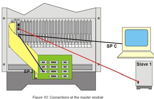
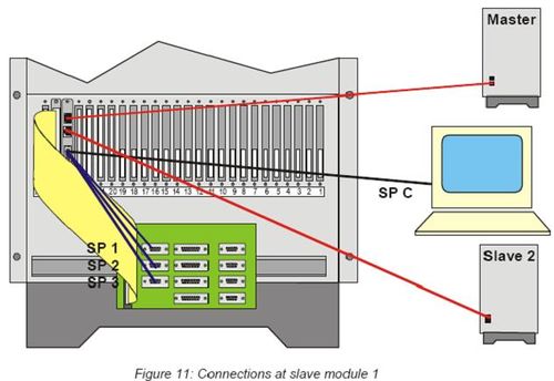
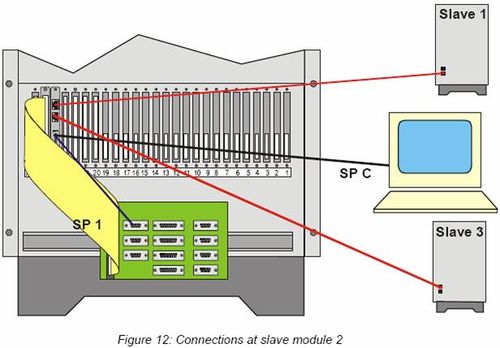
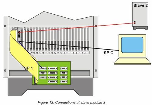
- Connect the RJ45-cable for the E1 links according to the drawings in
Figure 10, Figure 11, Figure 12 and Figure 13.
- Connect the ‘octopus’ serial ports SP 1, SP 2 and/or SP 3 according to the
drawings in Figure 10, Figure 11, Figure 12 and Figure 13.
- Switch the power ON.
- Watch the Line Indicator LED's on the AE1 board.
Lines that are in use must have the green LED lit, if not there is probably a cable or configuration problem. Note: If the AE1-cards in the different modules have been programmed before with a different configuration than default, the programming as described below must be done first.
Programming in the AE1-cards
Master module
Connect a terminal to the consol port of the AE1-card in the Master module (for details see AE1-card programming) and enter the following commands:
- clear (delete current programming and load default values)
- pattern master (sets the switch pattern of the AE1 card)
- refck master (note: If there is more than 1 AE1 card in the Master module, or if the E1 link is connected to an external network)
- save (save the configuration to flash memory)
- reset (reset the AE1 card)
Slave module 1
Connect the terminal to the consol port of the AE1-card in the Slave 1 and enter the following commands:
- clear (delete current programming and load default values)
- pattern slave1-4mod
- refck tl1
- save
- reset
Slave module 2
Connect the terminal to the consol port of the AE1-card in the Slave 1 and enter the following commands:
- clear (delete current programming and load default values)
- pattern slave2-4mod
- refck tl1
- save
- reset
Slave module 3
Connect the terminal to the consol port of the AE1-card in the Slave 1 and enter the following commands:
- clear (delete current programming and load default values)
- pattern slave-last
- refck tl1
- save
- reset
AlphaPro programming
The default behaviour of an AE1-card in positions 22, 23 and 24 is to provide multi-module audio rings. No programming is required.
Testing
- Connect stations to each module
- Reset the Master module by pressing the reset button on the APC and wait for
all modules to be up and running (this might take a minute or so, wait for the leds on all ASLT boards to become green)
- Make calls from the master module to each of the slaves; for each call audio should be heard in both directions (voice switched)
- If making calls between modules fail, carefully go through this chapter again


