ENA2060 Amplifier - Mounting and Installation
From Zenitel Wiki
This article describes the mounting and installation of the ENA2060 amplifier.
Mounting the Amplifier
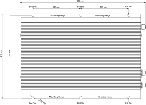
The amplifier’s mechanical construction is rigid enough to be mounted using the six slots in the mounting flanges to secure it to the mounting surface in the rail carriage.
For the rolling stock environment, it is considered good practice to mount support rails to better secure the amplifier.
- Use six 5 mm diameter bolts (M5) that are suitable for the mounting surface
- Secure the amplifier to the mounting surface by fastening the bolts in the slots on the mounting flanges (see Figure 1: Mounting Measurements)
- Mount the amplifier in a position that allows the free flow of air through its cooling fins
Amplifier Connectors
Ethernet Ports 1 & 2
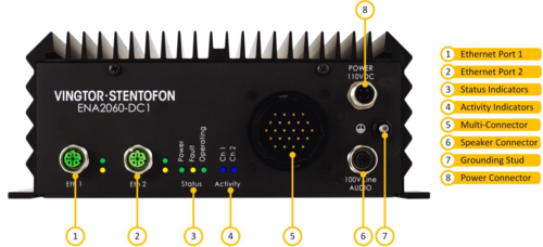
Ethernet Ports 1 & 2 are connected to the Train Communication Network (TCN) for exchanging data packets with the SIP server and other systems such as Network Monitoring System (NMS).
Port 1 is the main Ethernet connector while Port 2 is the backup Ethernet connector. The amplifier shall be connected to the network using a 4-pin M12 D-Coded male connector.
There are two LED indicators next to each Ethernet port:
- Link: Green LED is lit when the amplifier is connected to the network
- Activity: Yellow LED is lit when data is being transmitted
Status Indicators
The status indicators display the status of important parameters such as power supply and faults.
- Power: Green LED is lit when the system has power and is hardware controlled.
- Fault: Yellow LED is lit when the device has detected any faults in hardware or on the loudspeaker line (software controlled). The LED is lit when the processor is not running correctly (hardware controlled).
- Operating: Green LED is in low frequency flashing pattern to indicate CPU is running and system is OK.
Activity Indicators
- Activity: Blue LEDs (one for each audio channel Ch1 and Ch2) that will be lit when audio is present on the audio outputs.
Multi-Connector
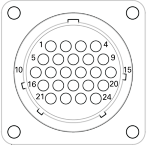
The Multi-Connector can be used for various functions as described below.
| Pin | Function | Description |
| 1 | UIC Pri + | UIC Priority Signal Input (+24VDC) |
| 2 | UIC Pri - | UIC Priority Signal Input (0VDC) |
| 3 | GPO1 + | 24 VDC Signal Output (physical volume controller override) |
| 4 | GPO1 - | 0 VDC Signal Output |
| 5 | UIC ON/OFF + | UIC On/Off Signal Input (Currently not in use) |
| 6 | UIC ON/OFF - | UIC On/Off Signal Input (Currently not in use) |
| 7 | GPI1 + | General Purpose Input |
| 8 | GPO2 + | 24 VDC Signal Output (physical volume controller override) |
| 9 | GPO2 - | 0 VDC Signal Output |
| 10 | UIC IN + | UIC Audio Signal Input |
| 11 | UIC IN - | UIC Audio Signal Input |
| 12 | GPI2 + | General Purpose Input (PTT key or audio triggered by other equipment) |
| 13 | GPI1 - | General Purpose Input (PTT key or audio triggered by other equipment) |
| 14 | CH1 0dB + (OUT) | Balanced Line Out for audio channel (inductive loop system) |
| 15 | CH1 0dB – (OUT) | Balanced Line Out for audio channel (inductive loop system) |
| 16 | LINE IN + | Audio Input, Line Input (local audio source) |
| 17 | LINE IN - | Audio Input, Line Input (local audio source) |
| 18 | GPI2 - | General Purpose Input (PTT key or audio triggered by other equipment) |
| 19 | CH2 0dB + (OUT) | Balanced Line Out for audio channel (inductive loop system) |
| 20 | CH2 0dB – (OUT) | Balanced Line Out for audio channel (inductive loop system) |
| 21 | MIC IN + | Audio Input for Microphone (ambient noise sensing or local announcement) |
| 22 | MIC IN - | Audio Input for Microphone (ambient noise sensing or local announcement) |
| 23 | MIC IN CHASSIS | |
| 24 | SPARE/TEST |
Audio Line Connector
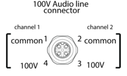
The Audio Line / Speaker connector is a 4-pin M12 A-Coded female connector that has two channels with 100-volt output per channel.
Audio Outputs
- 2 x 60W, 100V Audio
- Channel Outputs
- Monitoring Signals
Grounding Stud
This is an M4x20 stud for fixing a tab to the chassis and grounding the amplifier.

|
If the amplifier isn’t connected to ground, it will not be able to detect ground faults or short-circuits to ground. |
Power Connector
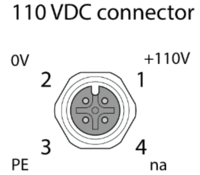
The power connector is a 4-pin M12 A-Coded male plug connector for 110 VDC power supply.
The green LED indicator for Power will be lit when the amplifier is powered up.

