DECT Server 2500
From Zenitel Wiki

|
Zenitel (Stentofon) does not provide any DECT product anymore. The information in this article may be outdated! |
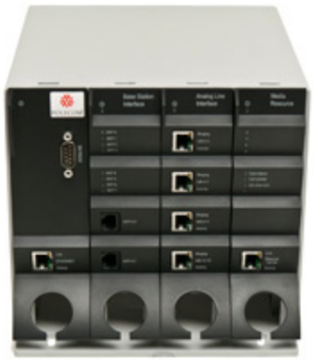
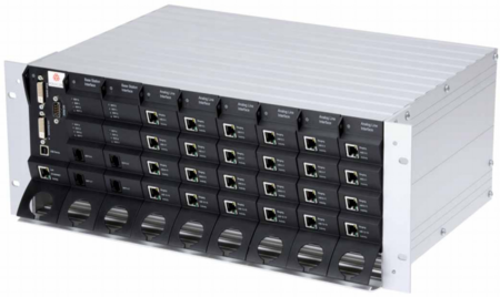
The STENTOFON DECT Server 2500 requires one CPU card and up to 3 interface cards for each shelf. If the needout grows a STENTOFON DECT Server 2500, then buy an empty STENTOFON DECT Server 8000 shelf and re-use the CPU card and interface cards from STENTOFON DECT Server 2500 in the STENTOFON DECT Server 8000 cabinet.
LED Overview
Table 1: LEDs Common to all Modules:
| LED Name | Location | Color | Description |
|---|---|---|---|
| Power | On top of all modules | Green | Steady green light when the power is on and the card is running. |
| Power | On top of all modules | Red | Flashing red light power up. Steady red light in case of error. |
On CPU card without link, the POWER LED is signalling the IP address of STENTOFON DECT Server 2500 by means of a sequence of LED flashing different colors.
Below is an example of behavior for IP address 127.0.1.101:
- LED steady green (“beginning of message”); LED off (break); LED flash blue (ignore this)
- break, LED flash green once (=”1”), break, LED flash green twice (=”2”), break, LED flash green 7 times (=”7”), break, LED flash red (=”.”)
- break, LED flash green once, longer (=”0”), break, LED flash red (=”.”)
- break, LED flash green once (=”1”), break, LED flash red (=”.”)
- break, LED flash green once (=”1”), break, LED flash green once, longer (=”0”), break, LED flash green once (=”1”), break
- LED steady green (“end of message”)
Table 2: CPU Card Ethernet Connector LEDs:
| LED Name | Location | Color | Description |
|---|---|---|---|
| Link | At the bottom of all modules | Green | Steady yellow when the Ethernet connection is in sync. |
| Activity | At the bottom of all modules | Red | Flashing green light when the Ethernet connection is active. |
Table 3: Base Station Interface Card:
| LED Name | Location | Color | Description |
|---|---|---|---|
| RFP 0-7 | Upper half - one LED for each RFP | Red | Steady red when there is power on the connector but not active RFP connect. Flashing red during power up sequence of RFP. |
| RFP 0-7 | Upper half - one LED for each RFP | Green | Steady green when RFP is in sync. Flashing green when at least one handset has a connection on the RFP. |
Table 4: Media Resource Card:
| LED Name | Location | Color | Description |
|---|---|---|---|
| Card Status | Upper half | Red | Steady red light in case of error. |
| Card Status | Upper half | Green | Steady green light when the power is on and the card is running. |
| Call Activity | Upper half | Green | Steady green when there are no active calls. Slow green flash when there's at least one active call using the Media Resource Card. |
| Idle Channels | Upper half | Green | Steady green when there are Idle channels available. |


