ONVIF Settings
From Zenitel Wiki
ONVIF is an open industry forum that provides and promotes standardized interfaces for effective interoperability of IP-based physical security products.
ONVIF profiles make it easy to recognize how ONVIF conformant devices and clients are compatible with one another. An ONVIF profile has a fixed set of features that must be supported by a conformant device and client. It ensures that a client that conforms to Profile S, for example, will work with a device that also conforms to Profile S. There are also conditional features, which are features that shall be implemented by an ONVIF device or ONVIF client if it supports that feature in any way, including any proprietary way. Optional functionalities are also defined, they do not need to be implemented but can if it's chosen. Clients and devices can support more than one ONVIF profile.
New from version 6.4.3.0:
- Supports bi-directional audio
- ONVIF features also available for Non-video Intercoms
Video Intercoms
Supported video devices
- TCIV
- TCIV+/TKIV+
ONVIF configuration
Some ONVIF settings are available from the station web interface.
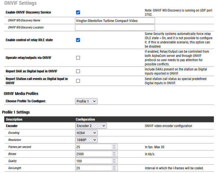
- Enable ONVIF Discovery Service - Enables UDP port 3702 on station firewall. Traffic to this port is used for WS-Discovery Service. If this setting is turned off, the station can not be discovered by any ONVIF client
- ONVIF WS-Discovery Name: Sets device name for WS-Discovery that will be shown in ONVIF client after the device is found
- ONVIF WS-Discovery Location: Sets device location for WS-Discovery that will be shown in ONVIF client after the device is found
- Enable control of relay IDLE state- Some Security systems automatically force relay IDLE state = On, and it is not possible to configure it. If this is an undesirable scenario, this option can be disabled
- Operate relay/outputs via ONVIF (ICX-AlphaCom mode only) - If enabled, Relay/Output can be controlled from both ICX-AlphaCom server and through ONVIF protocol so the user needs to pay attention for possible conflicts
- Report DAK as Digital Input in ONVIF: Call button pressed on a station is reported as Digital Input to a Video Management System.
- Report Station call events as Digital Input in ONVIF (default Disabled): Send station call status as Digital Inputs to a Video Management System. Supported call states are:
- In Conversation
- Ringing
- In call queue (ICX-AlphaCom mode only)
ONVIF Media Profiles ONVIF Media profiles control real-time video and audio streaming configurations. A media profile maps a video and audio source to a video and an audio encoder, PTZ and analytics configurations. Video turbines support only video encoder configuration which is described below. Video and audio sources cannot be configured since the device contains only one camera and microphone.
In most cases, media profiles are configured directly from Video Management System software (ONVIF client) and in that case, it is not recommended to manually change values below. The maximum number of Media Profiles which can be created is 50.
- Choose profile to configure - contains list of all profiles (built-in profiles and profiles created by ONVIF clients) for configuration. Profiles can be added and deleted only by ONVIF clients.
Encoder - each profile should be assigned with one ONVIF video encoder configuration. Possible options are Encoder 1, Encoder 2 or Encoder not set (This option is only used in situations when VMS creates media profile without video encoder and should never be manually selected).Encoder is defined with following parameters:
- Encoding - Defines which encoding type will be used:
- H264
- JPEG
- Resolution: Sets the pixel resolution:
- 1080P [H264 only]
- 720P [H264 only]
- 480P
- 240P
- Frames per second: Sets the framerate per second:
- 5-30 for H264
- 5-10 for JPEG
- Bitrate: Sets the bitrate which will be used in video stream (H264 only)
- Quality: Video quality parameter which is going to be used. It will have an effect for JPEG encoding only. Relative value for the quality of the video. A high value within supported quality range means higher quality
- GovLength: the interval in which the I-Frames will be coded. An entry of 2 indicates that every 2nd image is an I-Frame, and 3 only every 3rd frame, etc. The frames in between are coded as P or B Frames. Valid values are from 2 to 32767. Will have effect for H264 encoding only.

|
The login credentials used for ONVIF are different from the login credentials used for the web interface. To change the ONVIF login credentials, ONVIF Device Manager should be used. |
Non-Video Intercoms
Supported non-video devices
- TCIS/TKIS
- TFIE/TKIE
- TMIS
- TFIX
- V2 Master Stations
- IP Speakers
ONVIF configuration
Some ONVIF settings are available from the station web interface.
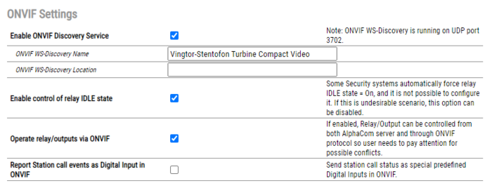
- Enable ONVIF Discovery Service - Enables UDP port 3702 on station firewall. Traffic to this port is used for WS-Discovery Service. If this setting is turned off, the station can not be discovered by any ONVIF client
- ONVIF WS-Discovery Name: Sets device name for WS-Discovery that will be shown in ONVIF client after the device is found
- ONVIF WS-Discovery Location: Sets device location for WS-Discovery that will be shown in ONVIF client after the device is found
- Enable control of relay IDLE state- Some Security systems automatically force relay IDLE state = On, and it is not possible to configure it. If this is an undesirable scenario, this option can be disabled
- Operate relay/outputs via ONVIF (ICX-AlphaCom mode only) - If enabled, Relay/Output can be controlled from both ICX-AlphaCom server and through ONVIF protocol so the user needs to pay attention for possible conflicts
- Report DAK as Digital Input in ONVIF: Call button pressed on a station is reported as Digital Input to a Video Management System.
- In Conversation
- Ringing
- In call queue (ICX-AlphaCom mode only)

|
The login credentials used for ONVIF are different from the login credentials used for the web interface. To change the ONVIF login credentials, ONVIF Device Manager should be used. |
Additional Information
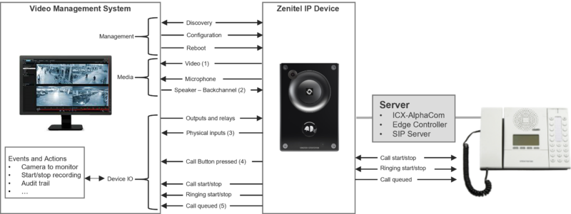
All Zenitel devices with a camera (TCIV and TCIV+) are certified to ONVIF Profile S. This allows the stations to be discovered by any ONVIF Profile S compliant VMS. As from VS-IS software version 6.4.3.0, a number of additional capabilities have been added:
- Support for DeviceIO
- Audio Backchannel, meaning audio from VMS to the device
In addition, some other major changes have been made:
- Audio only stations which can run VS-IS 6.4.3.0 are now able to generate a video stream, and are therefore compliant with ONVIF Profile S
- As a further enhancement to DeviceIO, station modes are made available as a logical input to the VMS and can then trigger function in that VMS
Non-Video Intercom stations as ONVIF Profile S compliant devices
The stations generate a video stream (a Zenitel logo) and can be discovered as any other camera. As with the TCIV and TCIV+, the microphone is also discovered as a camera capability.
Audio backchannel
VMS's which support this ONVIF feature will also discover the presence of the station's loudspeaker. This then gives the possibility for the VMS operator to directly send a voice message to the station. This would normally be used when the same message needs to be broadcast to all cameras featuring a loudspeaker and which cannot be reached in the normal Zenitel way, as they are not part of an ICX-AlphaCom, IC-EDGE or SIP system.
DeviceIO
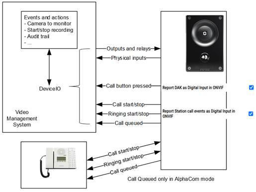
VMS's which support this ONVIF feature will be able to discover the presence of all inputs and outputs on the station. Inputs can be used to trigger actions in the VMS event handler. Control of the outputs can be directly by the operator, or as an action from the VMS event handler.
Report DAK as Digital Input in ONVIF
Other than the general purpose inputs which are available on the station, it is possible to have a DAK-button press reported as an input to the VMS. This can for instance be used as an additional way of signalling that there is somebody at the door, wanting to talk to the operator. (Turbine stations only)
Report station call events as Digital Input in ONVIF
Stations know the state they are in: in a call, ringing, in call requester mode. This state information is now available to the ONVIF module in the station software and can be used to provide a number of additional 'virtual' inputs. These inputs are discovered through DeviceIO, in the way any physical input is discovered. States that can be signaled to the VMS are:
- Call established - Call in progress input Activated
- Call ended - Call in progress input Deactivated
- Station in ringing mode - both for an outgoing (ringback) and incoming call - Call ringing input Activated
- Station ringing mode ended - Call ringing input Deactivated
- Station has made a call request or ringing group call (only when the station is in AlphaCom mode) - Call queued input Activated
- Station leaves call request or ringing group call mode (only when the station is in AlphaCom mode) - Call queued input Deactivated
Use cases that can be solved by these inputs are:
- Switching a camera to a monitor pane at the start of a conversation
- Starting and stopping video and/or audio recording
- Adding an entry in a the log for audit trail purposes
The order of inputs being reported
The following order, from first to last, is used to report the different inputs if enabled and available.
- Call Active
- Call Queued
- Call Ringing
- DAK 1....n
- Inputs 1....n
ONVIF Features
General
| Feature | Profile | Additional info | Supported from version | |||
| Turbine | TCIV+ | V2 Master stations | ||||
| Device Discovery | S | T | The ONVIF discovery name of a station shall be the name as known to it from its communication module (ICX-AlphaCom, IC-EDGE, SIP or the upcoming ICX-Next). | 6.4.3.0 | 6.4.3.0 | 6.4.3.0 |
| Network Configuration | S | T | Configuring network settings of the stations (DHCP, Static IP, Address, etc) | 6.4.3.0 | 6.4.3.0 | 6.4.3.0 |
| Media Profile Configuration | S | T | Configuration of media profiles in VMS | 6.4.3.0 | 6.4.3.0 | 6.4.3.0 |
| Media Transport | S | T | Defines the network protocol for streaming either RTP/UDP, RTP/TCP, RTP/RTSP/TCP or RTP/RTSP/HTTP/TCP | 6.4.3.0 | 6.4.3.0 | 6.4.3.0 |
Video
| Feature | Profile | Additional info | Supported from version | |||
| Turbine | TCIV+ | V2 Master stations | ||||
| Video streaming MJPEG/MJPEG4 | S | T | Motion JPEG (M-JPEG or MJPEG) is a video compression format in which each video frame or interlaced field of a digital video sequence is compressed separately as a JPEG image. | 6.4.3.0 | 6.4.3.0 | 6.4.3.0 |
| Video streaming H.264 | S | T | Also known as MPEG-4 Part 10 or Advanced Video Coding (MPEG-4 AVC), H.264 is defined as a block-oriented, compensation-based video compression standard that defines multiple profiles (tools) and levels (max bitrates and resolutions). A codec based on the H.264 standard compresses a digital video file (or stream) so that it only requires half of the storage space (or network bandwidth) of MPEG-2. Through this compression, the codec is able to maintain the same video quality despite using only half of the storage space. | 6.4.3.0 | 6.4.3.0 | 6.4.3.0 |
| Video streaming RTSP/RTP | S | T | The Real Time Streaming Protocol (RTSP) is a network control protocol used for establishing and controlling media sessions between endpoints. Clients of media servers issue commands such as play, record and pause, to facilitate real-time control of the media streaming from the server to a client (Video On Demand) or from a client to the server (Voice Recording). | 6.4.3.0 | 6.4.3.0 | 6.4.3.0 |
| Video Source Configuration | S | T | 6.4.3.0 | 6.4.3.0 | 6.4.3.0 | |
| Media Profile for Streaming Ready out-of-the-box | T | Allows usage of camera, microphones and speakers out of the box | 6.4.3.0 | 6.4.3.0 | 6.4.3.0 | |
| Imaging Settings | S | T | 6.4.3.0 | 6.4.3.0 | 6.4.3.0 | |
Audio
| Feature | Profile | Additional info | Supported from version | |||
| Turbine | TCIV+ | V2 Master stations | ||||
| Audio Streaming G.711 and AAC | S | T | 6.4.3.0 | 6.4.3.0 | 6.4.3.0 | |
| Audio Output Streaming G.711 and AAC | T | 6.4.3.0 | 6.4.3.0 | 6.4.3.0 | ||
| Birectional audio | T | 6.4.3.0 | 6.4.3.0 | 6.4.3.0 | ||
Events
| Feature | Profile | Additional info | Supported from version | |||
| Turbine | TCIV+ | V2 Master stations | ||||
| Event Handling pull point | S | T | Client creates a PullPoint subscription to the Event Service, allowing it to bypass firewall restrictions and WS-Endpoint provides PullMessages opration, wich is used by the client to retrieve notifications. | 6.4.3.0 | 6.4.3.0 | 6.4.3.0 |
| Media Profile Configuration Events | T | Mostly used for audit trail, events are notifing that the Media profile configuration has been changed | 6.4.3.0 | 6.4.3.0 | 6.4.3.0 | |
Additional
| Feature | Profile | Additional info | Supported from version | |||
| Turbine | TCIV+ | V2 Master stations | ||||
| Relay Outputs | S | T | Enables you to open door by triggering the relay on the station | 6.4.3.0 | 6.4.3.0 | 6.4.3.0 |


