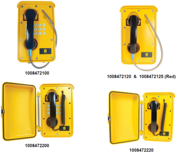
IP Heavy Duty V2 Connections
From Zenitel Wiki
Main connectors
To access these connectors the frontplate must be removed.
| LAN | 10/100 Mbps RJ-45 port for LAN (uplink) connection. Supports PoE (802.3af). Draws power from either spare line or signal line. |
| AUX | 10/100 Mbps RJ-45 ports for auxiliary equipment such as PC and IP camera. |
| Input/Output | Pluggable screw terminal |
| Local Power | If PoE is not available, the station can be powered from a 24-48 VDC local power supply, idle 1.8W, max. 12W |
Power Supply
The IP Heavy Duty Station supports Power over Ethernet (PoE, IEEE 802.3 a-f) where power can be drawn from either the spare line or signal line.
If PoE is not available, the IP Substation can be connected to a 24 VDC local power supply.
Connections
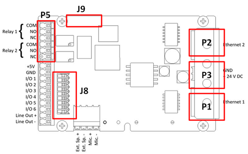
There are five relevant connectors on the IP heavy Duty station PCB:
- P1 RJ45 LAN port is for connecting to the data network
- P2: RJ45 AUX port is for connecting to auxiliary equipment such as a PC
- P3: Secondary power input 24-48VDC
- P5: 6-pin terminal for relay outputs for additional call indication, etc.
- Pin 1 COM relay 1 (Common)
- Pin 2 NO relay 1 (Normal Open)
- Pin 3 NC relay 1 (Normal Closed)
- Pin 4 COM relay 2(Common)
- Pin 5 NO relay 2 (Normal Open)
- Pin 6 NC relay 2 (Normal Closed)
- J8: 9-pin plug-on terminal for Handset.
- Pin 1/2: Hook switch
- Pin 4/5: Handset Mic
- Pin 6/7: Handset Speaker
- J9: Keyboard connector.
- See keyboard matrix article for details.
For more details see Turbine Extended Board Connectors.


