Display data receiver adjustment procedure for CRM-IV
From Zenitel Wiki
This procedure describes the adjustment of the data receiver in the CTLI (CRM-IV TouchLine Interface board), item number AC. The relevant stations are:
- 1007006100 CRM-IV Main modul with standard mic.
- 1007006101 CRM_IV Main modul with gooseneck mic.
- 1007006201 MCS, Multi Conference Station.
Necessary equipment to preform the adjustment:
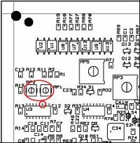
Oscilloscope with 10M ohm probe with a insulating transformer on the power supply.<br\> An AlphaCom exchange.<br\>A screwdriver suitable for the potmeter's RP1 and PR2.<br\>Connect the oscilloscape probe to pin 11 on U3 (this is the PLL, the 74HCT4046), and the oscilloscope ground to the B-wire close to the station (not more than 3 meters). Set the scope to 1 Volt/line vertical division and 2 usec/line horizontal divisjon. Adjust RP1 and RP2 until the waveform it is as shown on the figure, be accurate! Disconnect the board and reconnect after 2-3 seconds. Dial 789 (the AlphaCom will initialise automatically after a while but the 789 will work as well).<br\>The display should now reset.
(Oscilloscope waveform on my oscilloscope)<br\>This waveforms are very probe dependent. You have to experience the centre of the tolerance area yourself. Pay special attention to the slopes and the third peak on the curve. This peak shall only be flickering. Remember also the amplitude.

