Difference between revisions of "AE1 - AlphaCom Digital Network Board"
From Zenitel Wiki
| Line 58: | Line 58: | ||
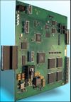
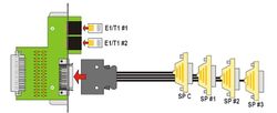
For the AlphaCom and AlphaCom 80+ there is a special filter card FBE1 with ordernr 1009509000. This card has a micro ribbon connector and 2 RJ45 connectors. The RJ45 connectors are industry standard 4-wire connection points for the E1/T1 interfaces. The micro ribbon connector gives access to all serial ports on the AE1-card. | For the AlphaCom and AlphaCom 80+ there is a special filter card FBE1 with ordernr 1009509000. This card has a micro ribbon connector and 2 RJ45 connectors. The RJ45 connectors are industry standard 4-wire connection points for the E1/T1 interfaces. The micro ribbon connector gives access to all serial ports on the AE1-card. | ||
| − | [[image: | + | [[image:AE1 - AlphaCom Digital Network Board - FBE1 with standard ’Octopus’-cable.jpg|thumb|250px|]] |
The filter card is delivered with an ‘Octopus’-cable on which the console and 3 general purpose serial ports are terminated. | The filter card is delivered with an ‘Octopus’-cable on which the console and 3 general purpose serial ports are terminated. | ||
Revision as of 13:08, 3 July 2007
The AE1 board provides AlphaCom with two E1 or T1 telecom interfaces. The AE1 board in an integrated board which fits into the AlphaCom back plane. The AE1 board converts between the internal SigmaDelta audio format and G.711 PCM. The AE1 board also has 7 RS232 ports, which can be transported in E1/T1 channels using a proprietary adaptation protocol. Finally the AE1 board can be configured to do transparent switching of timeslots between the two E1 links. The switching pattern is static only, must be configured using a terminal monitor.
Contents
Description
General
The AE1 card provides two independent E1/T1 interfaces. The board can be used in different configurations.
An E1 link provides 32 time-slots of 64 kbit/sec each; one slot is reserved for signalling purposes, 31 time-slots can be used for audio and data (maximum 7 data channels).
A T1 link provides 24 time-slots which can all be used for audio and data (maximum 7 data channels).
The connection to E1/T1 is a balanced 2x2-wire cable with an impedance according to E1/T1 standards. It is possible to set the board for E1 operation with a non-standard 100 Ohm impedance to match CAT5 cabling.
All available transmission and multiplexer equipment on the market with an E1/T1 interface can be used together with the AE1 card. Audio on the E1/T1 links is coded according to G.711 which gives telephony audio quality.
The card has access directly to 32 internal bi-directional audio interfaces on the AlphaCom backplane.
There are 8 RS232 serial data ports; one is reserved for a configuration PC and the other 7 are freely usable. An existing link with some spare time-slots can be passed through the AE1 card; AlphaCom audio and data can then be dropped and inserted from/to the spare time-slots. The card therefore also provides fractional E1/T1 multiplexing capabilities.
Exchange support
The AlphaCom and AlphaCom 80+ exchanges have support for the AE1-cards as follows:
- AlphaNet connectivity: Slots 22 and 23
- Multi-module linking: Slots 22, 23 and 24
The AlphaCom M supports the AE1-card as follows:
- AlphaNet connectivity: Slots 4 and 5
- Multi-module linking: Slots 4, 5 and 6
Towards the backplane of the exchange, the AE1-card interfaces to 32 bi-directional Sigma-Delta audio channels.
When used for AlphaNet connectivity, the AE1-card must be located in the master module (device 65); for multi-module use, an AE1 card must be present in each module. AE1 Installation and Commissioning Manual A100K10292/1.0 7
E1 and T1 description
E1/T1 are point-to-point, synchronous links.
- E1 has a speed of 2.048 Mbit/sec, which is divided into 32 timeslots of 64 kbit/sec each. Timeslot 0 is reserved for synchronisation, which means that 31 time slots are available for transmission of information. E1 has a 4-wire balanced interface (separate pairs for transmit and receive), with a 120 Ohm impedance.
- There is also a specification for a 75 Ohm unbalanced interface. The AE1-card does not support this interface, but 3rd-party equipment exists for matching between these 2 different interface specifications.
- The AE1-card can be set into a non-standard E1Cat5 mode, for use with 100 Ohm CAT5 cabling.
- T1 has a nominal speed of 1.536 Mbit/sec, which is divided into 24 timeslots of 64 kbit/sec each. In T1 there is no reserved timeslot for synchronisation; synchronisation is achieved by the addition of 1 bit to each 192-bit frame. This makes the real speed of the link 1.544 Mbit/sec. T1 has a 4-wire balanced interface (separate pairs for transmit and receive), with a 100 Ohm impedance.
Installation
The AE1-card is intended to be used for AlphaNet and multi-module linking of exchanges. The card can be used both for the audio and data transfer. The audio is taken directly from the backplane of the exchange. The data links are the same as normally used for data connections between exchanges and are to the serial ports available at the back of an exchanges, either on the Serial Port Connection Board (SPCB) in AlphaCom and AlphaCom 80+ exchanges, or directly on the backplane of the AlphaCom M. These serial ports need to be linked to serial ports on the AE1-card itself, after which the data can be transported over the E1/T1 links.
APC
The APC (in AlphaCom and AlphaCom 80+ exchanges) generates the clock signals for all cards inside the exchange. When an AE1-card is present, this clock will be synchronised to a clock signal on the AE1-card. On the APC, this synchronisation is only possible if the potentiometer related to the clock frequency is not in an extreme position (totally clockwise or anti-clockwise). In case of doubt, put the related potentiometer in the middle position.
[Details on synchronisation in the AlphaCom M exchange]
AlphaCom and AlphaCom 80+
In the AlphaCom and AlphaCom 80+ exchanges, AE1-cards can be placed in the following card position:
- Positions 22 and 23 for use in AlphaNet configuration. Cards for this use can only be placed in the master module of a multi-module exchange.
- Positions 22, 23 and 24 for use in multi-module linking. In this case AE1-cards must be present in the same card positions in all modules to be linked. Normally only card position 24 will be used for this purpose.
For the AlphaCom and AlphaCom 80+ there is a special filter card FBE1 with ordernr 1009509000. This card has a micro ribbon connector and 2 RJ45 connectors. The RJ45 connectors are industry standard 4-wire connection points for the E1/T1 interfaces. The micro ribbon connector gives access to all serial ports on the AE1-card.
The filter card is delivered with an ‘Octopus’-cable on which the console and 3 general purpose serial ports are terminated. One of these connectors is female and can be connected directly (or via a 1-to-1 serial cable, such as the cable for AlphaPro) to the 9-way serial port of a PC. The other 3 connectors are male and can be plugged directly into RS232 serial ports on the SPCB. These 3 connectors are labelled SP #1, SP #2 and SP #3, which refer to these three serial ports on the AE1-card. If more serial port connections are required to the AE1-card, a custom cable must be made.
=== Connections
The connections on the RJ45 connectors follows the industry standard for E1/T1 and is the same on both connectors:
- Tx+: 4
- Tx-: 5
- Rx+: 1
- Rx-: 2
- GND: 3, 6 and shield (normally this GND connection is not made, as E1/T1 is a 4-wire link and UTP cable can be used for E1 and T1 connections; these GND points are the same and connected together on the FBE1-card itself)
The pin assignment on the female console connector SP C is:
- Tx: 2
- Rx: 3
- Gnd: 5
The pin assignment on the 3 male serial port connectors SP #1, SP #2, SP #3 is:
- Tx: 3
- Rx: 2
- Gnd: 5
The pin assignment of the micro ribbon connector on the filter card is:
| Tx | Rx | Gnd | |
| SP C | 2 | 1 | 20 |
| SP #1 | 4 | 3 | 22 |
| SP #2 | 6 | 5 | 24 |
| SP #3 | 8 | 7 | 26 |
| SP #4 | 10 | 9 | 28 |
| SP #5 | 12 | 11 | 30 |
| SP #6 | 14 | 13 | 32 |
| SP #7 | 16 | 15 | 34 |
E1/T1 cable
For direct back-to-back connections between AE1-cards a crossed cable terminated at both ends with 8-pole RJ45 connectors is required. The interconnections between the connectors is as follows:
- Rx+: 1 ↔ Tx+: 4
- Rx-: 2 ↔ Tx-: 5
- Tx+: 4 ↔ Rx+: 1
- Tx-: 5 ↔ Rx-: 2
External references


