Difference between revisions of "AMC - AlphaCom Processor Board"
From Zenitel Wiki
| Line 2: | Line 2: | ||
== Features == | == Features == | ||
| − | |||
* Software on EPROM controls all functions | * Software on EPROM controls all functions | ||
* Customer programming on NVRAM-battery backup | * Customer programming on NVRAM-battery backup | ||
| Line 17: | Line 16: | ||
== Description == | == Description == | ||
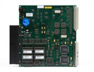
| − | + | This board contains software and hardware controlling the whole system. The board houses ASICs developed by STENTOFON: the MBI (Master Bus Interface) and SBI (Slave Bus Interface). It plugs into any of positions 20-25, recommended position is 25. The software on the board supports board monitoring which reports errors on all the other boards in the system. The reports can be printed out by connecting a printer to one of the serial ports. In addition there is the possibility to log technical alarms. All signals for external equipment is run to a connection board mounted on the connection field of the exchange. | |
| − | This board contains software and hardware controlling | ||
| − | the whole system. The board houses ASICs developed | ||
| − | by STENTOFON: the MBI (Master Bus Interface) and | ||
| − | SBI (Slave Bus Interface). | ||
| − | It plugs into any of positions 20-25, recommended | ||
| − | position is 25. | ||
| − | The software on the board supports board monitoring | ||
| − | which reports errors on all the other boards in the | ||
| − | system. The reports can be printed out by connecting a | ||
| − | printer to one of the serial ports. In addition there is the | ||
| − | possibility to log technical alarms. | ||
| − | All signals for external equipment is run to a connection | ||
| − | board mounted on the connection field of the exchange. | ||
== Data Connection Board == | == Data Connection Board == | ||
Revision as of 16:09, 10 February 2009
Features
- Software on EPROM controls all functions
- Customer programming on NVRAM-battery backup
- NVRAM backup on FLASH memory
- 8 serial ports supporting RS232 and RS422/485 (software controlled)
- Board monitoring
- Programmable/configurable from PC
- Real-time clock with battery backup
- Generates all system tones/gongs
- Display data generator
- Module controller
- Autoload button in front (used in combination with reset button on APC)
- 2 LEDs in front indicate status
Description
This board contains software and hardware controlling the whole system. The board houses ASICs developed by STENTOFON: the MBI (Master Bus Interface) and SBI (Slave Bus Interface). It plugs into any of positions 20-25, recommended position is 25. The software on the board supports board monitoring which reports errors on all the other boards in the system. The reports can be printed out by connecting a printer to one of the serial ports. In addition there is the possibility to log technical alarms. All signals for external equipment is run to a connection board mounted on the connection field of the exchange.
Data Connection Board
<br\><br\><br\><br\><br\><br\><br\><br\><br\><br\>
Technical Specifications
| Order Number | 100 9201 000 |
| Operation Voltage: | 5 and 15 V DC V DC |
| Dimensions (W x H x D) <br\><br\> | 10mm x 230mm x 263mm <br\> 0.39" x 8.97" x 10.26" <br\> Double Extended Europe Format |
| CUP type: | Motorola MC68HC000 (running at 16.384 MHz |
| RAM <br\> workspace: <br\> battery-backed NVRAM: | <br\> 512 Kb <br\> 512Kb |
| Indicator <br\> | Board status LED (green/amber/red) <br\> Red reset LED |


