AlphaCom Audio Switching Hardware
From Zenitel Wiki
This article contains a brief overview of the hardware involved in audio switching in an AlphaCom Exchange Module.
Audio Switching Hardware Infrastructure Overview
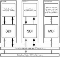
The first figure below shows the core elements of the infrasructure involved in audio switching. (Non-audio elements such as Slave Controllers are not shown. That the Master board also doubles as a Audio Board is not shown here either.) All audio switching is controlled from the software on the Master Controller. It accesses the Audio Switching Control Registers in the SBI through the MBI and the Backplane Data Bus. Each board may have from one to eight SBI’s and each SBI has eight identical “Digital Audio Channels” or “Channels” for short. Audio travels through the system as 1Mbit/s line-switched digital signals. The backplane has 16 bus lines, each with 16 timeslots, giving a total switching capacity of 256 one-way audio signals per Exchange Module. The default modulation is Stentofon-modified 1Msample/s Σ∆-modulation.(Audio with different modulations and synchronous or asynchronous data may be line-switched through the same infrastructure as well.)
The structure of each SBI Digital Audio Channel is shown in the figure below. Each of the SubChannel Time/Space Demultiplexers pick out one of the 256 possible signals on the Backplane Digital Audio Bus. The third demultiplexed signal is splitted into 2 signals on the Digital Audio Output. Each of the resulting 4 SubChannels have its separate On/Off control. The Primary (#0) SubChannel has a Fast (≈8ms) Fader instead of a direct switch to provide click-free switching. (The Fader may be bypassed in order to transparently forward audio with different modulations or data by sett ing theTransparent/ Faded Mode switch to Transparent). The Digital Audio Output is 8-way time division (TDM) multiplexed, providing the 4 available Digital Audio Output SubChannels plus 4 channels reserved for future use. The Digital Audio Input is non-multiplexed. It is put onto the Backplane Digital Audio Bus by the Audio Input Time/Space Multiplexer if and when the Audio Input On/Off Switch is set to On. It is possible by setting the Loopback/Normal to Loopback to feed the SubChannel 0 Signal back onto the Backplane Digital Audio Bus.(In order to provide a common feeding/fading point for multiple destinations and/or to provide click-free fading to signals destined for faderless subchannels.)

