Difference between revisions of "Display data receiver adjustment procedure for CRM-IV"
From Zenitel Wiki
| Line 4: | Line 4: | ||
* 1007006201 MCS, Multi Conference Station. | * 1007006201 MCS, Multi Conference Station. | ||
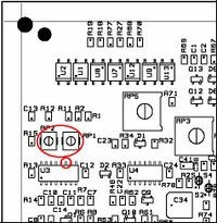
| − | '''Necessary equipment to preform the adjustment:''' | + | '''Necessary equipment to preform the adjustment:'''[[Image: Display data receiver adjustment procedure for CRM-IV.jpg|right|200px|thumb|CTLI placement]] |
| + | |||
Oscilloscope with 10M ohm probe with a insulating transformer on the power supply.<br\> An AlphaCom exchange.<br\>A screwdriver suitable for the potmeter's RP1 and PR2.<br\>Connect the oscilloscape probe to pin 11 on U3 (this is the PLL, the 74HCT4046), and the oscilloscope ground to the B-wire close to the station (not more than 3 meters). Set the scope to 1 Volt/line vertical division and 2 usec/line horizontal divisjon. Adjust RP1 and RP2 until the waveform it is as shown on the figure, be accurate! Disconnect the board and reconnect after 2-3 seconds. Dial 789 (the AlphaCom will initialise automatically after a while but the 789 will work as well).<br\>The display should now reset. | Oscilloscope with 10M ohm probe with a insulating transformer on the power supply.<br\> An AlphaCom exchange.<br\>A screwdriver suitable for the potmeter's RP1 and PR2.<br\>Connect the oscilloscape probe to pin 11 on U3 (this is the PLL, the 74HCT4046), and the oscilloscope ground to the B-wire close to the station (not more than 3 meters). Set the scope to 1 Volt/line vertical division and 2 usec/line horizontal divisjon. Adjust RP1 and RP2 until the waveform it is as shown on the figure, be accurate! Disconnect the board and reconnect after 2-3 seconds. Dial 789 (the AlphaCom will initialise automatically after a while but the 789 will work as well).<br\>The display should now reset. | ||
| − | |||
| − | |||
Revision as of 17:07, 9 August 2007
This procedure describes the adjustment of the data receiver in the CTLI (CRM-IV TouchLine Interface board), item number AC. The relevant stations are:
- 1007006100 CRM-IV Main modul with standard mic.
- 1007006101 CRM_IV Main modul with gooseneck mic.
- 1007006201 MCS, Multi Conference Station.
Necessary equipment to preform the adjustment:
Oscilloscope with 10M ohm probe with a insulating transformer on the power supply.<br\> An AlphaCom exchange.<br\>A screwdriver suitable for the potmeter's RP1 and PR2.<br\>Connect the oscilloscape probe to pin 11 on U3 (this is the PLL, the 74HCT4046), and the oscilloscope ground to the B-wire close to the station (not more than 3 meters). Set the scope to 1 Volt/line vertical division and 2 usec/line horizontal divisjon. Adjust RP1 and RP2 until the waveform it is as shown on the figure, be accurate! Disconnect the board and reconnect after 2-3 seconds. Dial 789 (the AlphaCom will initialise automatically after a while but the 789 will work as well).<br\>The display should now reset.

