|
|
| Line 1: |
Line 1: |
| | ==8022 - IP Substation== | | ==8022 - IP Substation== |
| − | This chapter gives details about connections and indications for:
| |
| − | *IP Substation [[Weather and Vandal Resistant IP Substation - 1008041100|1008041100]]
| |
| − | *IP Substation [[Weather and Vandal Resistant IP Substation for 3 gang Back Box - 1008051000|1008051000]]
| |
| − | *[[IP Heavy Duty Station - 1008072200]]
| |
| − | * IP Speaker - [[IP Ceiling Loudspeaker - 1401002100|1401002100]]/[[IP Horn Loudspeaker - 1401002500|1401002500]]
| |
| − | *[[IP Substation Kit - 1008090200]]
| |
| | | | |
| − | ===Connections===
| |
| − | [[File:IP Substation Main Board 1.PNG]]
| |
| − | <br/>
| |
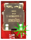
| − | ====LAN port P1 & AUX port P2====
| |
| − | <u>'''P1:'''</u>
| |
| − |
| |
| − | RJ45 LAN connector for 10/100 Mbit Ethernet connection. The station can be powered from this connection if the line supports Power over Ethernet (PoE).
| |
| − |
| |
| − | <u>'''P2:'''</u>
| |
| − |
| |
| − | RJ45 connector for auxiliary equipment like IP camera, PC or a second IP station. This port does not have an individual IP address. It does not carry power for auxiliary equipment.
| |
| − | [[File:IP Master Board 1.PNG|left|thumb|200px|P1/P2]]
| |
| − | <br style="clear:both;" />
| |
| − |
| |
| − | ====P3 - External Loudspeaker, Relay Output and External Power Input====
| |
| − | [[File:IP Substation Main Board 3.PNG|left|thumb|200px|P3]]
| |
| − | <br style="clear:both;" />
| |
| − | 6-pin plug-on screw terminal for external connections.
| |
| − | :*Pin 1/2: Connected to station loudspeaker. May also be used for 8-20 ohm / 2W external loudspeaker in parallel.
| |
| − | :*Pin 3/4: Internal NO (Normally Open) relay contact for door lock control, etc. Contact rating: Current: max 1A. Voltage: max 60 VDC. Power: max 30 W DC.
| |
| − | :*Pin 5/6: Connected to 24 VDC for station power when power is not distributed via LAN. Pin 6 is positive.
| |
| − |
| |
| − | '''About the relay:''' The relay actually has a change-over contact. On the screw terminal you have NO (Normal Open) contact only, but NC (Normal Closed) contact is also available between connector P3 - pin 4 and the soldering pad '''TP7'''.
| |
| − |
| |
| − | [[File:TP7 IP Sub.PNG|left|350px|thumb|Location of TP7 when using NC contact]]
| |
| − | <br style="clear:both;" />
| |
| − |
| |
| − | ====P4 - Inputs and Station LED====
| |
| − | 6-pin plug-on screw terminal for internal connections.
| |
| − | [[File:IP Substation Main Board 4.PNG|left|thumb|200px|P4]]
| |
| − | <br style="clear:both;" />
| |
| − | :*Pin 1/4: Call button no. 1
| |
| − | :*Pin 2/4: Call button no. 2 or logical input
| |
| − | :*Pin 3/4: Call button no. 3 or logical input
| |
| − | :*Pin 5/6: Station LED for call and message information
| |
| − |
| |
| − | ====TP1/TP2 - Line Output====
| |
| − | 0 dB, 600 ohm balanced audio output for connection to a power amplifier.
| |
| − |
| |
| − | '''Note:'''
| |
| − | The amplifier input MUST BE AN AC COUPLED INPUT (transformer, capacitors, etc.).
| |
| − | <br style="clear:both;" />
| |
| − |
| |
| − | ====TP9 - Output====
| |
| − | Logical output for a spare relay driver, max. 30 mA.
| |
| − | [[File:IP Substation Main Board 2.PNG|left|thumb|200px|P1/P2]]
| |
| − | <br style="clear:both;" />
| |
| − |
| |
| − | ====Additional DAK-keys, M- and C-key====
| |
| − | The [[IP Substation Board Connection|IP substation board]] supports input for digits 0 - 9, 10 [[DAK|DAK-keys]], as well as [[M-key]] and [[C-key]]. The inputs are available on soldering pads on the substation PCB.
| |
| − | [[Image:IP sub test pad location.png|left|thumb|300px|Location of soldering pads on the substation PCB]]
| |
| − | <br style="clear:both;" />
| |
| − | DAK 1: N115 + N112
| |
| − | DAK 2: N115 + N113
| |
| − | DAK 3: N115 + N114
| |
| − | DAK 4: N105 + N110
| |
| − | DAK 5: N105 + N111
| |
| − | DAK 6: N105 + N112
| |
| − | DAK 7: N105 + N113
| |
| − | DAK 8: N105 + N114
| |
| − | DAK 9: N105 + N115
| |
| − | DAK 10: N106 + N110
| |
| − | -------------------
| |
| − | M-key: N115 + N111
| |
| − | C-key: N115 + N110
| |
| − |
| |
| − |
| |
| − | '''Inputs for digit keys'''
| |
| − |
| |
| − | If more than 10 DAK keys are needed, it is possible to use the digit keys as DAK keys. The function needs to be enabled by the flag "Digit Key is DAK" in the [[Users_%26_Stations_%28AlphaPro%29#Station_Type|Users & Stations > Station Type]] menu in AlphaPro. The regular DAK keys are then moved to DAK 11 - 20.
| |
| − |
| |
| − | Digit 0: N111 + N110
| |
| − | Digit 1: N112 + N110
| |
| − | Digit 2: N112 + N111
| |
| − | Digit 3: N113 + N110
| |
| − | Digit 4: N113 + N111
| |
| − | Digit 5: N113 + N112
| |
| − | Digit 6: N114 + N110
| |
| − | Digit 7: N114 + N111
| |
| − | Digit 8: N114 + N112
| |
| − | Digit 9: N114 + N113
| |
| − |
| |
| − |
| |
| − | '''The keyboard matrix'''
| |
| − | [[Image:IP station Keyboard matrix.png|left|thumb|300px|The keyboard matrix of the IP station]]
| |
| − | <br style="clear:both;" />
| |
| − |
| |
| − | KEY0 = N110
| |
| − | KEY1 = N111
| |
| − | KEY2 = N112
| |
| − | KEY3 = N113
| |
| − | KEY4 = N114
| |
| − | KEY5 = N115
| |
| − | KEY6 = N105
| |
| − | KEY7 = N106
| |
| − | KEY8 = N107
| |
| | | | |
| | ===Indications=== | | ===Indications=== |

