Difference between revisions of "IP DECT Alarm Server - Quick Setup Guide"
From Zenitel Wiki
(→Configuration Restore & Backup) |
|||
| Line 1: | Line 1: | ||
{{A}} | {{A}} | ||
| + | |||
| + | {{obsolete}} | ||
| + | |||
| + | {{Note| Zenitel (Stentofon) does not provide any DECT product anymore. The information in this article may be outdated!}} | ||
| + | |||
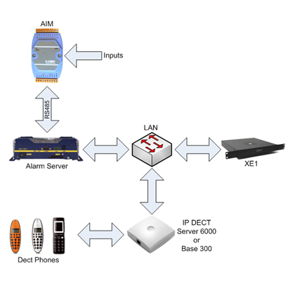
This article describes the minimum setup requirements to set up the IP DECT Alarm Server for use with the IP DECT Server 6000 and the IP DECT Base 300.<br/> For other more complex configuration please refer to: '''IP DECT Alarm Server Configuration Guide, A100K10677'''. | This article describes the minimum setup requirements to set up the IP DECT Alarm Server for use with the IP DECT Server 6000 and the IP DECT Base 300.<br/> For other more complex configuration please refer to: '''IP DECT Alarm Server Configuration Guide, A100K10677'''. | ||
[[Image:AlarmServer1.PNG|thumb|410px|Configuration Example]] | [[Image:AlarmServer1.PNG|thumb|410px|Configuration Example]] | ||
| Line 234: | Line 239: | ||
'''''NOTE! This will delete ALL configuration, including the Licenses and the IP settings. Always perform a backup before you do a restore of factory settings.''''' | '''''NOTE! This will delete ALL configuration, including the Licenses and the IP settings. Always perform a backup before you do a restore of factory settings.''''' | ||
| − | [[Category: | + | [[Category:Discontinued Accessories]] |
| − | |||
Latest revision as of 16:03, 8 November 2021

|
Zenitel (Stentofon) does not provide any DECT product anymore. The information in this article may be outdated! |
This article describes the minimum setup requirements to set up the IP DECT Alarm Server for use with the IP DECT Server 6000 and the IP DECT Base 300.
For other more complex configuration please refer to: IP DECT Alarm Server Configuration Guide, A100K10677.
Note! Do NOT perform a reset to factory default settings on an Alarm Server received from Zenitel. It has been preconfigured with licenses that will be erased. After 1st login create a backup file according to 6.3
Contents
Connecting the IP DECT Alarm Server
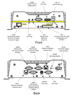
- Connect the power supply to the Alarm Server
- Connect the LAN2 port to a PC using a crossed ethernet cable or a switch/hub and patch cables via LAN.
- Turn on the power to the Alarm Server
The SYS LED indicator on the Alarm Server will light up a steady green.
Configuring the IP Interface and Web Server
Accessing the embedded web server
- Set up the PC to use an IP address on the 192.168.1.0 net range. For example 192.168.1.2.
- Enter the default Alarm Server IP address (192.168.1.1) in you browser address field.
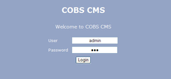
- Enter default user name and password in the login window.
- Default Username: admin
- Default Password: cms
- Click Login
- In the System menu, click the LAN tab, and enter an IP address suitable to your network in the LAN2 settings.
- Click Reset Required that appears on the bottom of the page. A new page opens, click Reset
- Login to the Alarm Server again, using the new IP address.
Configuring the IP DECT Process
Creating the IP DECT Process
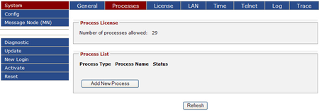
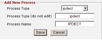
- Click System and then click Processes.
- Click Add New Process.
- Process Type: ipdect
- Process Type (do not edit): Leave as default: ipdect
- Process Name: IPDECT
- Click Save
- Click Reset Required that appears on the bottom of the page. A new page opens, click Reset
- Login to the Alarm Server again by clicking New Login in the left menu.
Configuring the IP DECT Process
After login, a new left menu item IPDECT will apear.
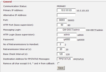
- Click IPDECT.
- Enter the following configuration data for the IP DECT Equipment (Server 6000 or Base 300):
- Primary IP Address: IP address of the IP DECT Equipment.
- Port: 56003.
- Messaging Login: GW-DECT/admin
- Password: ip6000
- Accept the default values for all other fields and click Save
- Click Reset Required that appears on the bottom of the page. A new page opens, click Reset
- Login to the Alarm Server again by clicking New Login in the left menu.
- After Login click IPDECT.
- Verify that Communication Status is now PRIMARY instead of DOWN.
Messaging Login and Password: The Messaging Login and Password are related to the IP DECT equipment. The above described login and password are defaults. Check your IP DECT equipment to see if these are changed from default. The check these settings, login to your IP DECT Server 6000 or IP DECT Base 300 and go to Configuration/Wireless Server
Communication Status
The Communication Status can be any of the following:
- DOWN = There is no communication with the IP DECT Equipment.
- PRIMARY = There is communication with the primary IP DECT Equipment.
- ALTERNATIVE = There is communication with the alternative IP DECT Equipment.
- Unknown = The Alarm Server is busy updating the status information - refresh the webpage.
Adding New Users/Handsets
To add new users/handsets:
- Click IPDECT and then click Users.
- Click Add New User.
- Enter the local number of the handset. (This is the same number as Username/Extension in the IPDECT user list.)
- Click Save.
- Repeat this procedure until you have registered all the handsets in the system.
- Att the bottom of the webpage, click Config Activation Required.
- Click Activate. You will be notified with: Activation Command sent.
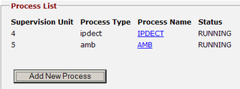
- Click System and then click Processes to verify that ipdect has Status RUNNING in the Process List box.
Installing and Configuring the Alarm Module
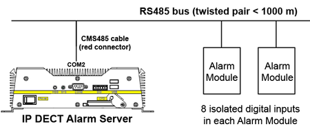
The Alarm Module is connected to the COM2 port on the IP DECT Alarm Server. The CMS485 connector/cable converts the RS485 bus to an RS232 signal. The CMS485 cable has 2 twisted pairs:
- Pair 1 (White/blue): RS485 Data Bus. The bus is polarized:
- White -> DATA- (D-)
- Blue -> DATA+ (D+)
- Pair 2 (White/Orange): Power Supply to the CMS485.
- White -> Ground (GND)
- Orange -> VDC (10-30V/10mA)
Depending on cable length, the number of modules that can be connected to the Alarm Server is as follows:
| Cable length (0.2.. twisted pair) | 0 m | 500 m | 1000 m |
| Number of modules at cable end | 14 | 8 | 2 |
Installing the Alarm Module
To install the Alarm Module:
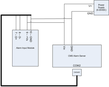
- Connect the power supply to (9) GND and (10) V+ on the Alarm Module.
- Supply voltage can be between 10-30 VDC (Power consumtion is 0.2W).
- Depending on proximity, you can connect up to 14 Alarm Modules on the same RS485 bus connected to the COM2 port on the Alarm Server.
- Each Alarm Module has 8 inputs but can have up to 14 inputs.
- Connect the inputs 1 to 8 to the desired external equipment, either with or without external power.
There are two methods of connecting inputs to the Alarm Module:
1: Push button (output from external device) using the same power supply as the Alarm module.
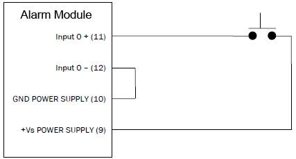
2: Push button (output from external device) using an external power supply.
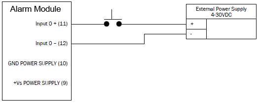
Adding the AMB Process
Login to the Alarm Server (CMS).
- Click System and then click Processes
- Click Add New Process.
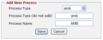
- Process Type: amb
- Process Type (do not edit): Leave as default
- Process Name: AMB
- Click Save
- Click Reset Required that appears on the bottom of the page. A new page opens, click Reset
- Login to the Alarm Server again by clicking New Login in the left menu.
After login, a new left menu item AMB will apear.
- Click AMB, and then click Net.
- Click Search Net.
A pop-up window will appear with the message: Searching for Modules, Please Wait!. The AMB will now scan the RS485 bus for all possible addresses. The procedure may take up to 30 seconds. The search results will then be displayed.
All new modules have address 01 at delivery. As a result, this address is not allowed for use in the AMB
as it is reserved for adding new modules. Connect the new module (one at a time) to the Alarm Server.
The module should appear under address 01. Select the new desired address for module 01 from the dropdown list (2 to 15 - any existing module addresses are excluded from the list) and click Set. The AMB will now change the address of the module. Make a new search to verify that the new address has been set. To connect more modules to the Alarm Server, repeat the procedure in this section.
Configuring the AMB Process
- Click AMB and then click Modules.
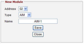
- Click Add New Module
- Address: 02
- Type: AIM
- Name: AIM-1
- Click Save
- Click AMB and then click Modules and the new module will be displayed.
- Click Reset Required that appears on the bottom of the page. A new page opens, click Reset
- Login to the Alarm Server again by clicking New Login in the left menu.
Configuring Alarm Module Inputs
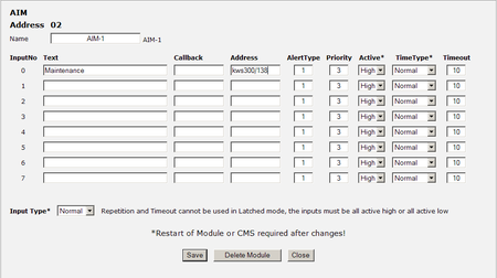
- In the left menu click AMB, and then click Modules.
- Click on the module address of the module you want to configure.
- Enter the desired text in the Text field for the correct input.
- Enter the Address for the message, either for one specific handset, or an Alias (optional).
- Enter the Alert Type 0-9.
- Enter the Priority 1-3. Priority works in the sense that when the server is overloaded with messages, those with higher priorities will be sent out first.
- Select the right input level for Active signal from the dropdown list. This is the input level that causes an activation of the input, and can be set to High (>4V) or Low (<1V).
- Leave the other settings as default.
- Click Save
- Click Close when done.
- At the bottom of the webpage, click Config Activation Required, and then click Activate
- Click AMB, then Modules and check the Modules list to see whether there is communication between the AMB and the module under Status (Up or Down).
- Verify that the AMB process has Status RUNNING by clicking System and then clicking Processes.
Sending a Test Message
To send a test message:
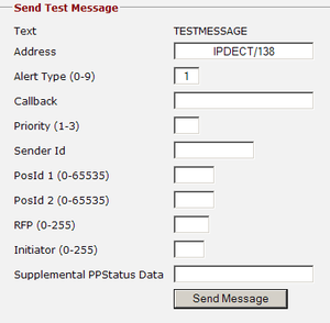
- Click Diagnostic and then click Test Message.
- In the Address field, enter the individual user/handset in the format IPDECT/user number, or enter the name of a group of handsets (Alias, optional).
- In the Alert Type (0-9) field, enter the wanted alert type. If left blank, the default alert type is used.
- Leave all other fields blank.
- Click Send Message.
- The text TESTMESSAGE will be sent to the selected user (or to a group of users (Alias, optional)
Optional
Alias
A group of handsets is called an Alias.
This is useful if an input shall trigger a message to several handsets. Example: an emergency backup power system fails, and a closing contact triggers. This is linked to input 1 and should send a text message to all handsets to personell in the maintenance departement.
Creating an Alias
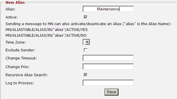
- Click Message Node (MN), and then click Alias.
- Click Add New Alias
- Enter the name for the Alias, for example Maintenance. Leave all other fields as is.
- Click Save and then click Close.
- Click Config Activation Required that appears at the bottom of the webpage, and then click Activate.
Configuring an Alias
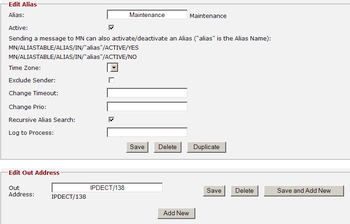
- Click Message Node (MN), and then click Alias.
- Click the Alias name, e.g. Maintenance.
- Click Add New in the Edit Out Address box.
- Enter the Out Address e.g. IPDECT/138
- Click Save. Repeat the procedure for all the handsets you want to include in Maintenance.
- Click Close when done.
At the bottom of the webpage, click Config Activation Required and then click Activate. Note! The handsets configured as Out Address must be added in IPDECT/Users.
Alert Types
The alert types define how the message shall be indicated in the handset. There are 10 alert types, numbered 0-9. To view the default alert types simply click IPDECT and then click Alert Types.
To edit the Alert Type, click the Alert Type number, e.g. 9.
Configuration Restore & Backup
To back up and restore the configuration file:
Click Config and then click File.
The Configuration file is an XML file.
To back up the Configuration file to your computer:
- Click Download in the Download Configuration box.
- Click Save to save the file to your computer.
To upload the Configuration file:
- Click Browse in the Upload Configuration box.
- Select the XML file.
- Click Upload.
To erase the configuration and revert to factory settings:
- Click Erase in the Erase Configuration box. A warning pop-up window will be displayed.
- Click Erase again to confirm.
NOTE! This will delete ALL configuration, including the Licenses and the IP settings. Always perform a backup before you do a restore of factory settings.


