Difference between revisions of "Philips M100"
From Zenitel Wiki
(→Updating the exchange) |
(→Adding new module to existing M100 exchange) |
||
| Line 112: | Line 112: | ||
(LBB 7103/05). <br/> | (LBB 7103/05). <br/> | ||
See M100 documentation for further details. | See M100 documentation for further details. | ||
| + | |||
| + | =Programming in AlphaPro (AlphaCom)= | ||
| + | The programming procedures described in this section is for setting up a single-module M100 exchange with an AlphaCom XE7. The setup procedures for equipment other than the above will differ somewhat from that described in this section. | ||
| + | |||
| + | ==Installation== | ||
| + | Install and start AlphaPro on your PC. | ||
| + | [[File:M100Int 16.PNG|thumb|AlphaPro Logo]] | ||
| + | |||
| + | ==Creating Nodes== | ||
| + | <u>'''Create a network and an AlphaCom node:'''</u> <br/> | ||
| + | [[File:M100Int 18.PNG|thumb]] | ||
| + | * From the menu bar, select '''[+]''' next to the '''Select Network''' drop-down menu. | ||
| + | * Enter '''2'''in the '''Node Number''' field | ||
| + | ** This node number must be higher than the M100 node number | ||
| + | * Select '''AlphaCom E from the '''Node Type''' drop-down menu | ||
| + | Enter other relevant data for the network. <br/> | ||
| + | [[File:M100Int_17.PNG]] <br/> | ||
| + | |||
| + | <u>'''Create an M100 node:'''</u> | ||
| + | [[File:M100Int_19.PNG|thumb]] | ||
| + | * From the menu bar, select '''[+]''' next to the '''Select Exchange''' drop-down menu | ||
| + | * Enter '''1''' in the '''Node Number''' field | ||
| + | ** This node number must be lower than the AlphaCom node number | ||
| + | * Select '''M100 Node''' from the '''Node Type''' drop-down menu | ||
| + | Enter other relevant data for the node. <br/> | ||
| + | [[File:M100Int_20.PNG]] <br/> | ||
| + | |||
| + | ==Define Data Communication== | ||
| + | [[File:M100Int 21.PNG|thumb]] | ||
| + | [[File:M100Int 22.PNG|thumb]] | ||
| + | * Select the AlphaCom node created previously | ||
| + | * Click the '''Exchange & System''' icon | ||
| + | * Click '''Net Routing''' | ||
| + | * Click '''Insert''' | ||
| + | * Highlight '''M100''' as the destination node and click '''Select''' | ||
| + | * Under '''Primary Route''', select '''M100 Link''' from the '''ACDP Link''' drop-down list | ||
| + | * Click '''Close'''' to close the Net Routing window | ||
| + | [[File:M100Int 23.PNG]] <br/> | ||
| + | |||
| + | ==Define Audio Connections== | ||
| + | [[File:M100Int 21.PNG|thumb]] | ||
| + | * Click the '''Exchange & System''' icon | ||
| + | * Click '''Net Audio''' | ||
| + | * Click '''Insert''' | ||
| + | * Highlight '''M100''' as the destination node and click '''Select''' | ||
| + | * Enter '''31''' in the '''Physical no.''' field | ||
| + | * Enter '''1''' in the '''Channel''' field | ||
| + | * Click '''Close''' to close the Net Audio window | ||
| + | [[File:M100Int 24.PNG]] <br/> | ||
| + | Repeat this procedure for the number of audio channels desired according to the table below. <br/> | ||
| + | [[File:M100Int_25.PNG]] <br/> | ||
Revision as of 11:34, 16 March 2012
Contents
Software Requirements
AlphaCom
The AMC-IP board must have software version 10.20 or higher. Latest software version is always recommended. The latest version for AlphaCom can be downloaded here.
The AMC-IP software includes the following software routines:
- The software daemon (M100d) which is running the M100 format with the AlphaCom XE main software.
- The software daemon AMCd which is running the AlphaCom XE Main Software
- The embedded web server which is used to configure AMCd and M100d (AlphaWeb).
M100
The software type and version is not critical as long as it supports 6-digit dialling.
Supported SW:
6U Computer Card LBB 7103/07: SW LBB 7216/83
3U Computer Card LBB 7103/06: SW LBB 7216/83
FC Card LBB 7110/13:          SW LBB 7202/28
Programming Tools
AlphaCom
The programming tool for AlphaCom is AlphaPro software version 10.28 or higher.
Download the latest version here.
AlphaPro is used to identify M100 modules as nodes in the AlphaNet and to configure the AGA audio routing.
M100
The programming tool for M100 is SysMain software version 3.0. It is available on request from alphasupport@zenitel.com.
Audio Link Interface

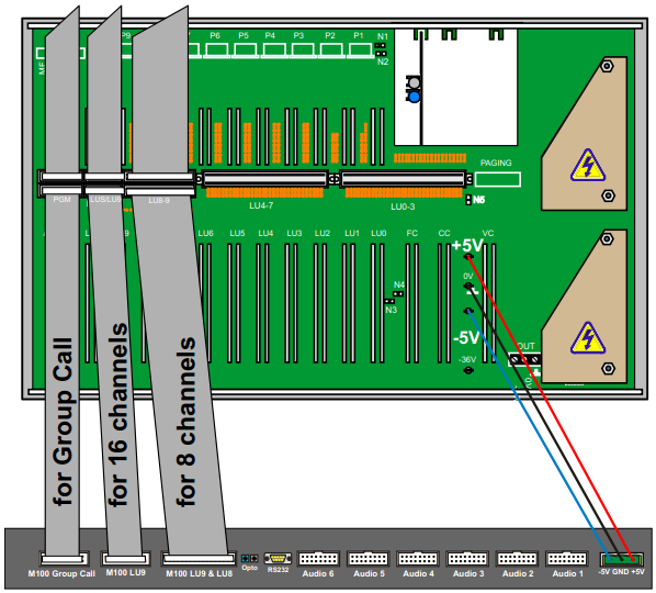
The Audio Link Interface Unit is powered from the M100 module. Solder a 3-wire power cable to the three solder studs labeled +5V, 0V (GND), and -5V on the M100 backplane. Connect the other free end of the cable to a 3-way plug-in screw terminal that connects to the receptor labeled -5V GND +5V at the back of the Audio Link Interface Unit.
Data Connection
AlphaCom
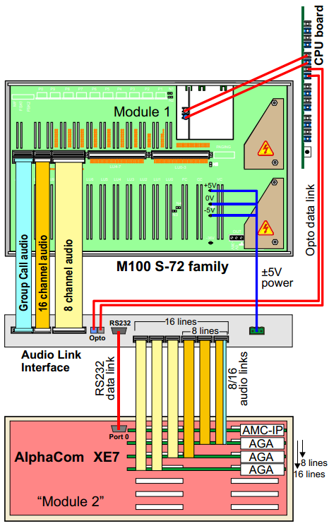
Use a crossed RS232 cable with female 9-pin D-sub connectors at each end to connect the AlphaCom XE7 serial Port 0 to the Audio Link Interface connector labeled AlphaCom RS232.
M100
The M100 system communicates via optical fiber cables. The opto cable (LBB 7103/61) connects from the M100 Computer Card (LBB 7103/05) to the Audio Link Interface Unit. On the Computer Card, connect the opto cable to the connector labeled Module 1 (assuming that the M100 is a single-module system). The other end of the opto cable connects to the receptors labeled M100 Serial - Opto at the back of the Audio Link Interface Unit.
Audio Connection
AlphaCom
Group Call & 8 Audio Channels
To connect 8-channel Group Call audio for AlphaCom:
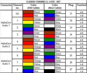
- Cut off one connector on three 8-pair flat cables.
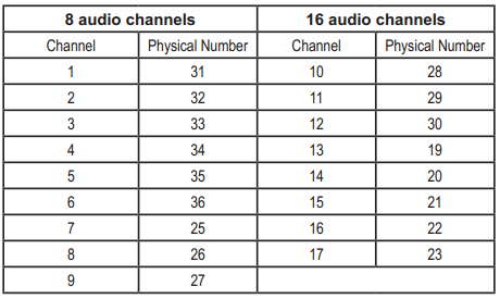
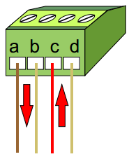
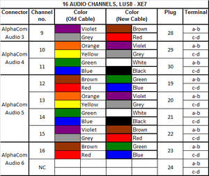
- Connect the free ends to nine 4-way plug-in screw terminals according to table 1.
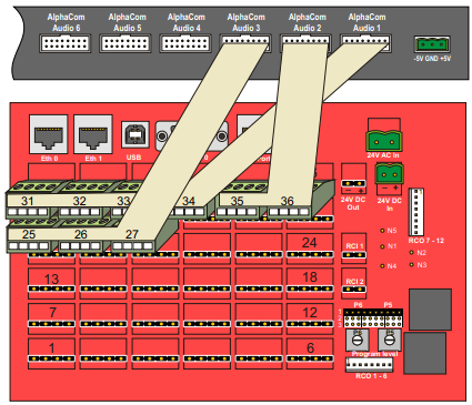
- Connect the plugs to the corresponding connectors at the back of the AlphaCom XE7 Audio Server according to table 1.
- Connect the other end of the cables to the connectors at the back of the Audio Link Interface labeled AlphaCom Audio 1 to 3.
Group Call & 16 Audio Channels
To connect 16-channel Group Call audio for AlphaCom:
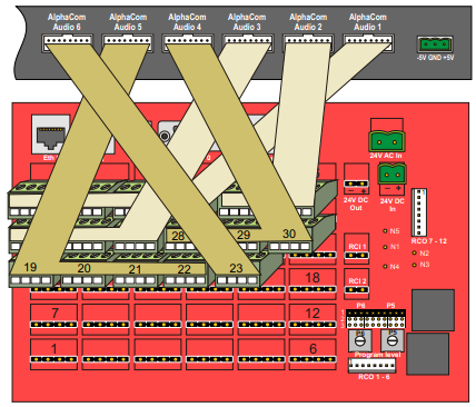
- Cut off one connector on six 8-pair flat cables.
- Connect the free ends to seventeen 4-way plug-in screw terminals according to tables 1 and 2.
- Connect the plugs to the corresponding connectors at the back of the AlphaCom XE7 Audio Server according to tables 1 and 2.
- Connect the other end of the cables to the connectors at the back of the Audio Link Interface labeled AlphaCom Audio 1 to 6.
M100
Group Call
To connect Group Call audio for M100:
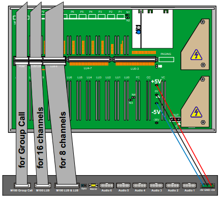
- Connect a 20-core ribbon cable to the free connector labeled PGM at the back of the M100 module.
- Only the Group Call channel is transmitted and not the Program Distribution channels.
- Connect the other end to the connector at the back of the Audio Link Interface labeled M100 Group Call.
8 audio channels - 1 LUS board
To connect 8-channel audio for M100:
- Connect a 32-core ribbon cable to the free connector labeled LU8-9 at the back of the M100 module.
- Connect the other end to the connector at the back of the Audio Link Interface labeled M100 LU9 & LU8.
16 audio channels - 2 LUS boards
To connect 16-channel audio for M100:
- Connect a 16-core ribbon cable to the free connector labeled LUS/LU9 at the back of the M100 module.
- Connect the other end to the connector at the back of the Audio Link Interface labeled M100 LU9.
Programming in SysMain (M100)
Installation
Install and start SysMain on your PC.
Getting Started for New M100 System
- Select File -> New
- A setup wizard will start
- Click Next
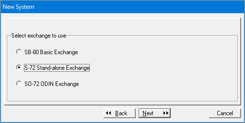
- Select S-72 Stand-alone Exchange and click Next
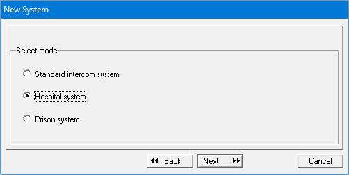
- Select the type of system of your choice. In this example Hospital System is selected.
- Click Next
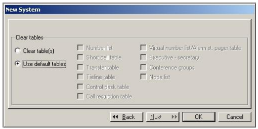
- Select Use default tables and click OK
Setting system parameters
After setup is completed, the Update system information window automatically opens:
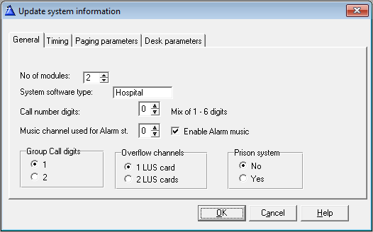
- Set No. of modules to 2.
- Select the number of LUS cards installed.
- Click OK
Updating the exchange
In the menu, click Exchange and select Send data to the exchange
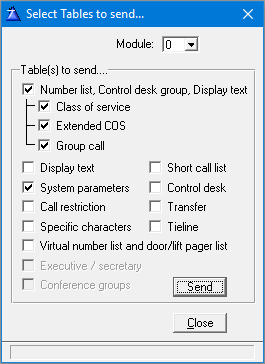
- Select Module 0
- Enable Number list and System parameters
- Click Send
Adding new module to existing M100 exchange
When there is an existing M100 exchange with modules that are already defined, a new module has to be added before connecting to the Audio Link Interface. In the Update system information window in SysMain, activate a new module by increasing the number of existing modules by one:
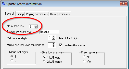
The opto cable connects to the first available output. If no outputs are available, an ACIA card (LBB 7103/56) has to be installed. The ACIA card requires that the exchange is already fitted with the Computer Card
(LBB 7103/05).
See M100 documentation for further details.
Programming in AlphaPro (AlphaCom)
The programming procedures described in this section is for setting up a single-module M100 exchange with an AlphaCom XE7. The setup procedures for equipment other than the above will differ somewhat from that described in this section.
Installation
Install and start AlphaPro on your PC.
Creating Nodes
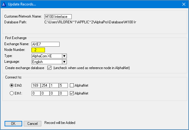
Create a network and an AlphaCom node:
- From the menu bar, select [+] next to the Select Network drop-down menu.
- Enter 2in the Node Number field
- This node number must be higher than the M100 node number
- Select AlphaCom E from the Node Type drop-down menu
Enter other relevant data for the network.
Create an M100 node:
- From the menu bar, select [+] next to the Select Exchange drop-down menu
- Enter 1 in the Node Number field
- This node number must be lower than the AlphaCom node number
- Select M100 Node from the Node Type drop-down menu
Enter other relevant data for the node.

Define Data Communication
- Select the AlphaCom node created previously
- Click the Exchange & System icon
- Click Net Routing
- Click Insert
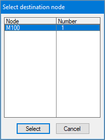
- Highlight M100 as the destination node and click Select
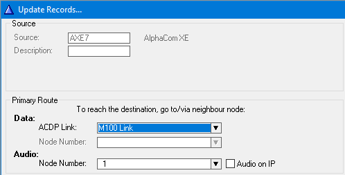
- Under Primary Route, select M100 Link from the ACDP Link drop-down list
- Click Close' to close the Net Routing window
Define Audio Connections
- Click the Exchange & System icon
- Click Net Audio
- Click Insert
- Highlight M100 as the destination node and click Select
- Enter 31 in the Physical no. field
- Enter 1 in the Channel field
- Click Close to close the Net Audio window
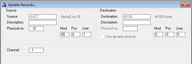
Repeat this procedure for the number of audio channels desired according to the table below.
