RIO - Remote Input/Output Unit
From Zenitel Wiki
Features
- 8 inputs - programmable to normally open or closed.
- 18 outputs
- Provides connectors for 3 MRBD Multi-Relay Boards with drivers.
- Easy connection in mounting box (included)
- Easy programming of the unit from the AlphaPro programming tool for PC.
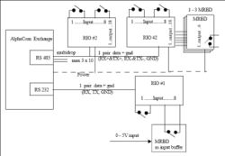
- Connects by RS485 or RS232 to the AlphaCom exchange.
- When using RS485, up to 10 units can be chained.
- With RS485 the maximum distance from the exchange is 1 km.
- Status LED on the board.
- Built-in error indication
- Power must be supplied locally if the RIO unit is mounted outside the exchange room.
Description
The Remote Input Output Unit (RIO) is a flexible way of connecting digital inputs/outputs to the AlphaCom exchange. The devices can operate on point to point connections (RS 232) or on a multidrop bus (RS 485)
The RIO Unit has two circuit boards - the RIO board and the IICE board (Inter IC Connection Board).
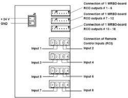
Each RIO unit has 8 inputs and 18 outputs. The outputs are connected to the relayboard MRBD. Each MRBD has 6 relays. If all 18 outputs are used, 3 MRBD boards are required. The RIO and the MRBD are interconnected with a cable included with the MRBD. The RIOs can be mounted away from the exchange room, thus reducing cabling. If response time is critical (<2sec), as in audio control, the internal RCIs and RCOs in the exchange should be used.
The RIO is used for:
- Distribution of remote control outputs (RCOs) from the AlphaCom exchange such as door opening, video camera control, additional call indications etc.
- Connection of technical alarm inputs (RCIs). The alarm inputs can be signals coming from temperature control devices, fire panels, burglar alarms etc. The AlphaCom itself provides 6 RCI (2 in ACM) inputs, this can be increased to 140 RCIs by using the maximum number of RIOs.
Connectors and Switches
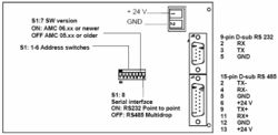
RIO Board
IIEC Board
Serial Interface setting on the RIO Board - Switch S1: 8
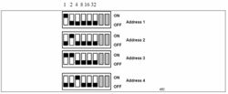
Address setting - Switch S1:1-6
RS 495 bus
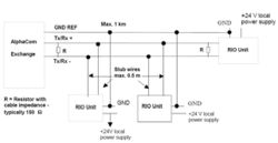
The RS 485 bus can be maximum 1 km long. Up to 10 RIOs can be connected to the bus. The data pair must be terminated in each end with a resistor equal to the cable impedance, typically 150-ohm.
When connecting the RIOs to the bus, wire stubs must be kept as short as possible, preferably less than 0.5 m. All RIOs must be connected to a common GND reference conductor.
NOTE: Use local power supply for each RIO.
NOTE: Do NOT use the GND reference for power distribution.
Installation
General Description
The RIO unit should be installed in a dry and dust free environment. There is easy access to connectors and DIP-switches through openings in the front plate. A 15 pin D-sub with 0,5m of color-coded cable is provided for the RS485 connector. The unit can be mounted to mounting rails.
The RIO unit can be installed in the following locations:
- At the connection field of the exchange.
- Elsewhere in the same room.
- Up to 1km away through the RS485 bus, with 10 units chained together.
- Up to 50 m away through the RS232 bus.
Note: if the RS232 connection is used, surveillance and debugging of the RIO is not possible.
Power supply
The RIO unit can use power from the exchange if it is installed in the exchange room; otherwise it must be powered locally.
Cable requirements
RS485
RIO mounted in the exchange room :
- 2 wires for data.
- 2 wires for power from exchange
RIO mounted outside the exchange room:
- 2 wires for data
- 1 wire for ground reference
- 2 wires for local power.
RS232
- 2 wires for data.
- 1 wire for ground reference
- 2 wires for power from exchange/local power
Installation of the RIO system
Power supply
If local power is used, a regulated 24VDC /1A power supply is necessary.
Note; this is NOT supplied from Stento.
If power from the exchange is used, a Power Distribution Board in the exchange is necessary. See Installation and Commissioning Manual, A100K10002.
<center>CATION</center>
<center>Do not extend power cables from the PDB outside the exchange rack environment. Use</center>
<center>local power for remote installation of equipment.</center>


