Difference between revisions of "TCAS Connections"
From Zenitel Wiki
(→Wiring) |
(→Second Call Button) |
||
| (5 intermediate revisions by the same user not shown) | |||
| Line 2: | Line 2: | ||
[[File:TCAS Connections 1.PNG|thumb|right500px|TCAS substation - Rear side]] | [[File:TCAS Connections 1.PNG|thumb|right500px|TCAS substation - Rear side]] | ||
This article describes connection details of the analog intercoms [[TCAS-1]], [[TCAS-2]] and [[TCAS-3]]. | This article describes connection details of the analog intercoms [[TCAS-1]], [[TCAS-2]] and [[TCAS-3]]. | ||
| − | |||
| − | |||
| − | |||
| − | |||
| − | |||
| − | |||
| − | |||
| − | |||
| − | |||
| − | |||
| − | |||
| − | |||
| − | |||
| − | |||
| − | |||
| − | |||
| − | |||
| − | |||
| − | |||
| − | |||
==Wiring== | ==Wiring== | ||
| Line 29: | Line 9: | ||
* 0.9 mm wires: 4.0 km | * 0.9 mm wires: 4.0 km | ||
| − | The station line | + | The station line can be connected in to ways: |
| + | * By means of an RJ45 connector at the rear side of the station, or | ||
| + | * By using the plugable screw connector | ||
| + | Connection using the RJ45 connector: | ||
[[File:WiringAnalogTCAS.png|thumb|left|800px]] | [[File:WiringAnalogTCAS.png|thumb|left|800px]] | ||
<br style="clear:both;" /> | <br style="clear:both;" /> | ||
| Line 40: | Line 23: | ||
<br> | <br> | ||
| − | == Second Call | + | == Second Call Button == |
| − | The station is prepared for a | + | The station is prepared for a second external call button (DAK 2). The button can be connected between the A-wire and the lower leg on D6 on the print (highlighted in the image above). |
| − | |||
| − | |||
[[File:TCAS Connections 2.PNG|thumb|left|500px]] | [[File:TCAS Connections 2.PNG|thumb|left|500px]] | ||
<br style="clear:both;" /> | <br style="clear:both;" /> | ||
| − | |||
[[Category: Turbine Connections]] | [[Category: Turbine Connections]] | ||
Latest revision as of 12:51, 31 August 2018
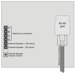
This article describes connection details of the analog intercoms TCAS-1, TCAS-2 and TCAS-3.
Wiring
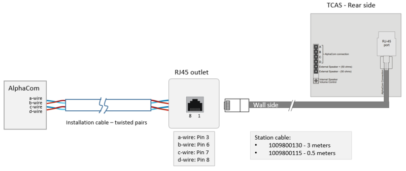
The cabling from the AlphaCom server to the intercom station is star wiring. Two twisted pairs of wires are required. The maximum distance depends on the cable diameter:
- 0.5 mm wires: 1.4 km
- 0.6 mm wires: 2.0 km
- 0.9 mm wires: 4.0 km
The station line can be connected in to ways:
- By means of an RJ45 connector at the rear side of the station, or
- By using the plugable screw connector
Connection using the RJ45 connector:

|
The station cable is not a 1:1 cable! |
For details on connection at the AlphaCom server side, see ASLT - AlphaCom Subscriber Line Board
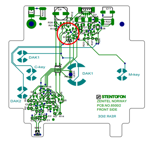
Second Call Button
The station is prepared for a second external call button (DAK 2). The button can be connected between the A-wire and the lower leg on D6 on the print (highlighted in the image above).


