Difference between revisions of "Tamper switch"
From Zenitel Wiki
(→Configuration) |
|||
| Line 4: | Line 4: | ||
==Configuration== | ==Configuration== | ||
| − | === For a single station == | + | === For a single station === |
| − | In [[AlphaPro]], create this event for the Tamper Switch: | + | In [[AlphaPro]], create this event for the Tamper Switch, setting the cell station as the event owner: |
[[file:TamperSwitchEvent.png|500px|thumb|left|Event handler configuration]] | [[file:TamperSwitchEvent.png|500px|thumb|left|Event handler configuration]] | ||
<br style="clear:both;" /> | <br style="clear:both;" /> | ||
| Line 11: | Line 11: | ||
{{code2|$STM L110 L101 U100 'TAMPER CELL 10'}} | {{code2|$STM L110 L101 U100 'TAMPER CELL 10'}} | ||
| + | === For all stations === | ||
| + | |||
| + | === Verify that I/O 3 is set as an input === | ||
The IP Substation must have I/O number 3 defined as an input (default). | The IP Substation must have I/O number 3 defined as an input (default). | ||
[[file:TamperSwitchWeb.png|500px|thumb|left|Advanced AlphaCom -> I/O Settings]] | [[file:TamperSwitchWeb.png|500px|thumb|left|Advanced AlphaCom -> I/O Settings]] | ||
| Line 17: | Line 20: | ||
| − | + | ||
| + | |||
| + | |||
==Mounting== | ==Mounting== | ||
Revision as of 14:42, 1 December 2022
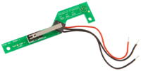
The IP Vandal Resistant Substation with TKIE has the possibility to be fitted with a tamper switch. Making it possible to raise an alarm if the station is dismounted from the backbox.
Contents
Configuration
For a single station
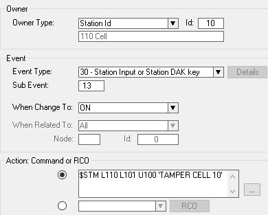
In AlphaPro, create this event for the Tamper Switch, setting the cell station as the event owner:
Action commands:
$STM L110 L101 U100 'TAMPER CELL 10'
For all stations
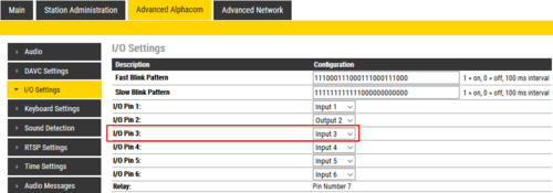
Verify that I/O 3 is set as an input
The IP Substation must have I/O number 3 defined as an input (default).
Mounting
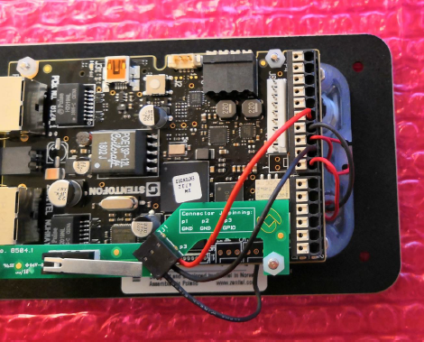
Mounting instruction on Tamper Switch for IP Vandal Resistant Substation TKIE
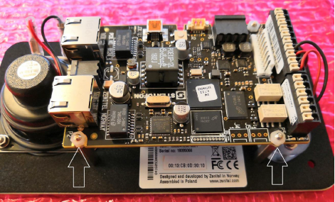
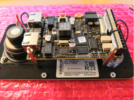
Step 1: Remove the two nylon nuts shown below
Step 2: Attach the supplied spacers
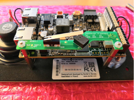
Step 3: Mount the tamper switch board
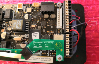
Step 4: Move the button GND wire from the the TKIE board to the tamper switch board
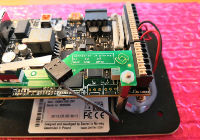
Step 5: Use the supplied wires to connect GND and Input 3 as shown below


