Turbine Configuration
From Zenitel Wiki
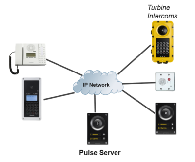
The Turbine IP stations can be set to operate in one out of three different modes:
- AlphaCom mode
- SIP mode
- Pulse mode
Contents
AlphaCom mode
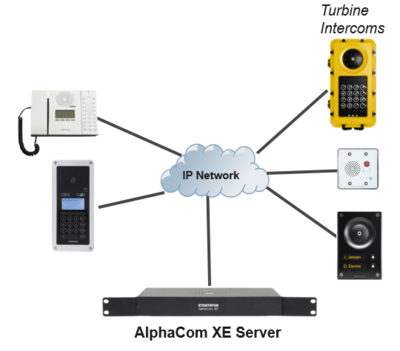
The Turbine Stations are connected to the AlphaCom XE server/exchange which is the heart of the VINGTOR-STENTOFON security and communication system. The communication between the AlphaCom XE exchange and the Turbine Stations utilize the VINGTOR-STENTOFON CCoIP® protocols. The AlphaCom XE server/exchange includes all main service configurations for the IP stations and only a minimum configuration is needed to be carried out on the actual station.
Logging into the Station
Access the station by logging into the web interface using a standard web browser:
- 1. Open a web browser
- 2. In the browser’s address bar, type the station IP address and press the ENTER key
- - The station login page will be displayed.
To log into the station:
- 1. Click Login
- 2. Enter the default User name: admin
- 3. Enter the default password: alphaadmin
The Station Information page will now be displayed, showing the IP station configuration and status.
Note that the user interface and parameters displayed in the following sections are dependent on the Turbine station type (Compact, Industrial or Ex) selected.
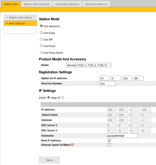
Main Settings
- Click Station Main > Main Settings to access the page for configuring station mode and IP parameters.
Station Mode: Select the Use Alphacom radio-button.
Product Model And Accessory: Depending on the type of Turbine hardware, there are different Product models and accessories to choose from. Find your model here: Turbine Station Models
Registration Settings:
- AlphaCom IP-address: Enter the IP address of the AlphaCom server to which the IP station is to be registered
- Directory Number: Enter the directory number of the station. This must match the directory number defined in the AlphaCom server
- - If a directory number is not entered, the station will register with its MAC address. The MAC address is found on the Station Information page and needs to be entered in the AlphaCom server using the AlphaPro PC tool
IP Settings:
- DHCP – Select this option if the IP station shall receive IP Settings from a DHCP server.
- Static IP – Select this option if the IP station shall use a static IP address. Enter values for:
- - IP-address
- - Subnet-mask
- - Gateway
- - DNS Server 1 (option for network administration)
- - DNS Server 2 (option for network administration)
- - Hostname (option for network administration)
- Read IP Address: Check the Read IP Address box to enable an unregistered station to speak the IP address when the call button is pressed. "Read IP Address" is default enabled.
- Enable RSTP (for Industrial & Ex stations): Check the Enable RSTP box to enable RSTP. RSTP is only required when using redundant networking
- Ethernet Speed 10 Mbits/s: Default Ethernet speed is 100 Mbit/s unless switch is configured to 10 Mbit/s
Click Save followed by Apply to apply the new configuration settings.
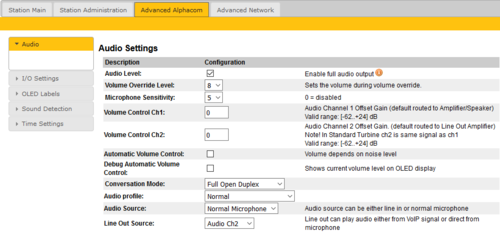
Audio Settings
To configure audio settings select Advanced Alphacom > Audio from the menu
- Select or set values for the parameters:
- - Volume Override Level
- - Microphone Sensitivity
- - Automatic Volume Control
- - Debug Automatic Volume Control
- - Conversation Mode
- - Audio profile
- - Audio source
- - Line Out Source
Volume Override Level: Select the Volume Override Level in the range 0 to 8 from the drop-down box. The default setting is 8. This setting determines the volume to be used in the station when receving audio and the Volume Override feature is activated, see Volume Override for more details.
Microphone Sensitivity: Select the sensitivity level in the range 0 to 7 from the drop-down box. The default setting is 5. If used as a local PA panel, a setting in the 1 to 3 range will reduce the chance of acoustic feedback (howling)
Volume Control Ch1 & Ch2: Offset Gain (default routed to Amplifier/Speaker). Valid range: -62 to +24 dB
NOTE!This feature must be used with caution as incorrect settings may severely degrade the performance of the echo-cancelling algorithm.
Automatic Volume Control: Check the box to enable automatic volume control that is adjusted according to the noise level
Debug Automatic Volume Control: Check the box to show current volume level on OLED display
Conversation Mode: For this parameter, there are five options:
- Full Open Duplex: Normal mode with echo cancellation.
- Robust Duplex: Option used when open duplex fails due to excessive speaker loudness, microphone overload or very high nonlinear distortions.
- Half Duplex Switching: Switches speech direction depending on who speaks the loudest.
- Push-To-Talk: Half-duplex communication. Initially the microphone is shut off. Push the M-button to open the microphone, and release to listen. (Only applicable to stations with M-key)
- Open: Full Open Duplex without echo cancellation
Audio Profile: This parameter has the following options:
- Normal
- Noisy Environment
- Very Noisy Environment
- Advanced. Note!: Advanced options are for experienced users only! Incorrect settings may severely degrade the acoustic performance and intelligibility. Use with care!
- See Turbine Audio Profiles for more details
Audio Source: This parameter has the following options:
- Normal Microphone
- Line In (for Turbine Extended intercoms only)
Line Out Source: Let you choose if the Speaker signal (the VoIP stream from AlphaCom) also should be played on the Line Out output, or if the Microphone signal should be routed to the Line Out output.
When used with an external amplifier (and speakers), use Speaker. When using the built-in microphone as an input to another system, use Microphone.
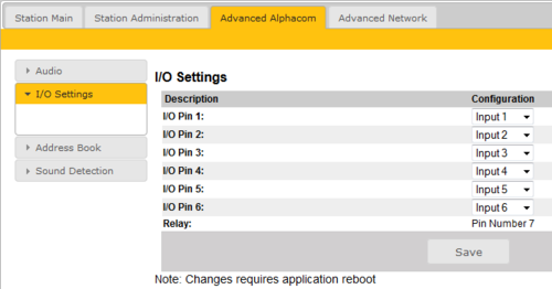
I/O Settings
These settings let you choose in an I/O should be used as an Input or as an Output. By default all I/O's are set as Inputs.
- Select Advanced AlphaCom > I/O Settings from the menu
- Select either Input or Output options from the drop-down box for I/O Pins 1 to 6.
OLED Labels
Applies to TCIS-4 and TCIS-5. See article OLED Labels for more details.
Keyboard Settings
Applies to TFIE-x and TFIX-x. See article TFIE Keyboard Settings for more details.
Address Book
Applies to TCIS-6 and TCIV-6. See article Address Book for more details.
Sound Detection
The Sound Detection, also known as Voice Activity Detection (VAD) samples the audio level from the microphone located in the IP Station. If the audio level meets defined criterias an action in AlphaCom can be triggered.
Read more about Sound Detection.
Time Settings
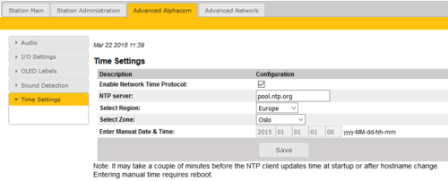
- Select Advanced AlphaCom > Time Settings from the menu
Time Settings: You can enable Network Time Protocol, select the time zone and set the hostname or the IP address of the NTP server.
SIP mode
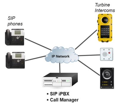
SIP (Session Initiation Protocol) is the de facto standard for IP telephony. The VINGTOR-STENTOFON SIP intercom stations are specially built for easy integration with any iPBX system. The VINGTOR-STENTOFON SIP Stations are custom-made IP intercom stations that can integrate with any iPBX system.
The Vingtor-Stentofon Intercom Manager Tool (VS-IMT) can be used to configure multiple intercoms in a network. The following sections describe configuration procedures using the web interface of the station.
Logging into the Station
Access the station by logging into the web interface using a standard web browser:
- 1. Open a web browser
- 2. In the browser’s address bar, type the station IP address and press the ENTER key
- - The station login page will be displayed.
To log into the station:
- 1. Click Login
- 2. Enter the default User name: admin
- 3. Enter the default password: alphaadmin
The Station Information page will now be displayed, showing the IP station configuration and status.
Note that the user interface and parameters displayed in the following sections are dependent on the Turbine station type (Compact, Industrial or Ex) selected.
Main Settings
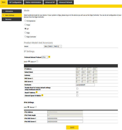
- Click Station Main > Main Settings to access the page for configuring station mode and IP parameters.
Station Mode: Select the Use SIP radio-button.
Product Model And Accessory: Depending on the type of Turbine hardware, there are different Product models and accessories to choose from. Find your model here: Turbine Station Models
IP Settings:
- DHCP – Select this option if the IP station shall receive IP Settings from a DHCP server.
- Static IP – Select this option if the IP station shall use a static IP address. Enter values for:
- - IP-address
- - Subnet-mask
- - Gateway
- - DNS Server 1 (option for network administration)
- - DNS Server 2 (option for network administration)
- - Hostname (option for network administration)
- Read IP Address: Check the Read IP Address box to enable an unregistered station to speak the IP address when the call button is pressed. "Read IP Address" is default enabled.
- Enable RSTP (for Industrial & Ex stations): Check the Enable RSTP box to enable RSTP. RSTP is only required when using redundant networking
- Ethernet Speed 10 Mbits/s: Default Ethernet speed is 100 Mbit/s unless switch is configured to 10 Mbit/s
Click Save followed by Apply to apply the new configuration settings.
SIP Settings
Select SIP Configuration > SIP Settings to access the page for configuring SIP parameters.
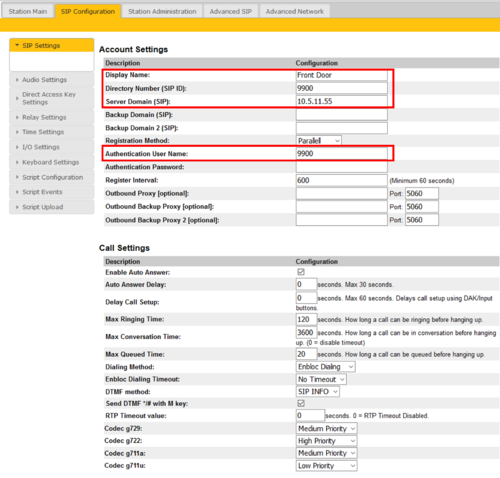
Account Settings
- Display Name: Enter a name that will be shown on the display at the remote party.
- Directory Number (SIP ID): This is the identification of the station in the SIP domain, i.e. the phone number for the station. This parameter is mandatory. Enter the SIP ID in integers according to the SIP account on the SIP domain server.
- Server Domain (SIP): This parameter is mandatory and specifies the primary domain for the station and is the IP address for the SIP server (e.g. Asterisk or Cisco Call Manager). Enter the IP address in regular dot notation, e.g. 10.5.2.138.
- Backup Domain (SIP): This is the secondary (or fallback) domain. If the station loses connection to the primary SIP domain, it will switch over to the secondary one. Enter the IP address in regular dot notation.
- Backup Domain 2 (SIP): This is the tertiary SIP domain used as backup in case the primary and secondary domains fail.
- Registration Method:
- Parallel: The station will register to the primary, secondary and tertiary SIP server domains at the same time.
- Serial: The station will always try to register to the first available SIP server domain, starting with the primary domain, followed by the secondary and the tertiary domains.
- Top-Down: This is the same as for Serial registration except that it will always revert to the SIP domains with the higher priority if available. In decreasing order of priority, the primary SIP domain has the highest priority, followed by the secondary domain and the tertiary domain.
- Cisco: This is for the Cisco environment only with Publisher/Subscriber/SRST setup, where the station is normally registered to Publisher. The Subscriber should be assigned as the secondary SIP domain, and SRST gateway as the tertiary domain.
- Authentication User Name: This is the authentication user name used to register the station to the SIP server. This is required only if the SIP server requires authentication and is normally the same as the SIP ID.
- Authentication Password: The authentication user password used to register the station to the SIP server. This is required only if the SIP server requires authentication
- Register Interval: This parameter specifies how often the station will register, and reregister in the SIP domain. This parameter will affect the time it takes to detect that a connection to a SIP domain is lost. Enter the values in number of seconds from 60 to 999999. The default interval is 600 seconds.
- Outbound Proxy [optional]: Enter the IP address of the outbound proxy server in regular dot notation, e.g. 10.5.2.100
- Port: Enter the port number used for SIP on the outbound proxy server. The default port number is 5060.
- Outbound Backup Proxy 1&2 [optional]: Enter the IP address of the backup outbound proxy server in regular dot notation, e.g. 10.5.2.100
Call Settings
- Enable Auto Answer: If enabled, the station will answer automatically, and if not, the station will ring.
- Auto Answer Delay: The auto answer can be delayed from 1 to 30 seconds. Default value is 0 which means the station will answer instantly.
- Delay Call Setup: This only applies to inputs and DAK buttons. The button must be pressed and held for the set time. Maximum is 60 seconds.
- Max Ringing Time: How long a call can be ringing before hanging up.
- Max Conversation Time: How long a call can be in conversation before hanging up.
- Max Queued Time: How long a call can be queued before hanging up.
- Dialing Method: Choose between Enbloc Dialing or Overlap Dialing.
- Enbloc Dialing Timeout: Timeout period is from 1 to 9 seconds.
- DTMF method: Choose between SIP INFO or RFC 2833 to select DTMF signalling method.
- Send DTMF */# with M key: Check box to enable
- RTP Timeout value: This cancels a call if the station does not receive RTP packets from the remote party. Enter values in the range 0-9999 seconds. The default setting is 0 which means RTP timeout is disabled.
- Codec g729 / Codec g722 / Codec g711a / Codec g711u: Options are Not Used, Low Priority, Medium Priority, High Priority.
After entering all the desired values, click Save and then click Reboot to enable the SIP settings.
Audio Settings
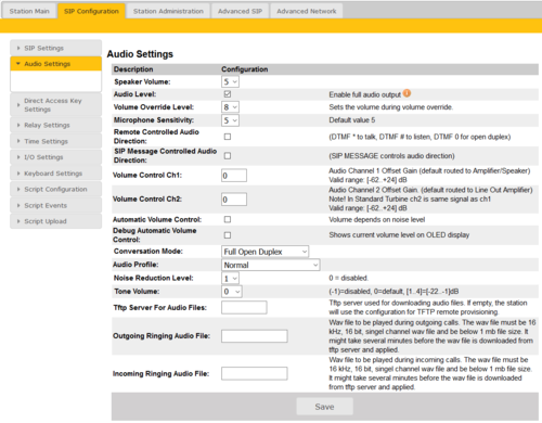
Select SIP Configuration > Audio Settings to access the page for configuring Audio parameters.
- Speaker Volume: Select the volume level in the range 0 to 7 from the drop-down menu. Default setting is 5
- Volume Override Level: Select the volume override level in the range 0 to 8 from the drop-down menu.
- Microphone Sensitivity: Select the sensitivity level in the range 0 to 7 from the drop-down menu. Default setting is 5
- If used as a local PA panel, a setting in the 1 to 3 range will reduce the chance of acoustic feedback (howling).
- Remote Controlled Audio Direction: This acts as simplex mode. This feature is activated after the first DTMF * or # is received from the remote station. Send DTMF * to talk and # to listen. Check the box to enable this function.
- SIP Message Controlled Audio Direction
Check the box to enable the following messages:
- SIP MESSAGE “Audio_receive_only”: Turns the microphone off and loudspeaker on
- SIP MESSAGE “Audio_send_only”: Turns microphone on and loudspeaker off
- SIP MESSAGE “Audio_send_receive”: Turns both microphone and loudspeaker on
- Default setting is an unchecked box (i.e. the function is disabled)
- Volume Control Ch1 & Ch2: Offset Gain (default routed to Amplifier/Speaker). Valid range: -62 to +24 dB
- Note: This feature must be used with caution as incorrect settings may severely degrade the performance of the echo-cancelling algorithm.
- Automatic Volume Control: Check the box to enable automatic volume control that is adjusted according to the noise level
- Debug Automatic Volume Control: Check the box to show current volume level on OLED display (for TCIS-4/TCIS-5/TCIS-6)
- Conversation Mode
- Full Open Duplex: Normal mode with echo cancellation
- Robust Duplex: Option used when open duplex fails due to excessive speaker loudness, microphone overload or very high nonlinear distortions.
- Half Duplex Switching: Switches speech direction depending on who speaks the loudest
- Push-To-Talk: Half-duplex communication. Initially the microphone is shut off. Push the M-button to open the microphone, and release to listen. (Only applicable to stations with an M-button)
- Open: Full Open Duplex without echo cancellation
- Audio Profile: For this parameter, there are 4 options:
- Normal
- Noisy Environment
- Very Noisy Environment
- Advanced (Note: Advanced options are for experienced users only! Incorrect settings may severely degrade the acoustic performance and intelligibility. Use with care!)
- Noise Reduction Level: The higher the noise reduction level the more deterioration there is in audio quality.
- Tone Volume
- Tone type: ringtone
- Valid range: -1 to 4 (-1 means the function is disabled)
- Tftp Server For Audio Files: The TFTP server for downloading audio files
- Outgoing Ringing Audio File: WAV file played during outgoing calls
- Incoming Ringing Audio File: WAV file played during incoming calls
After entering all the desired values, click Save.
Direct Access Key Settings
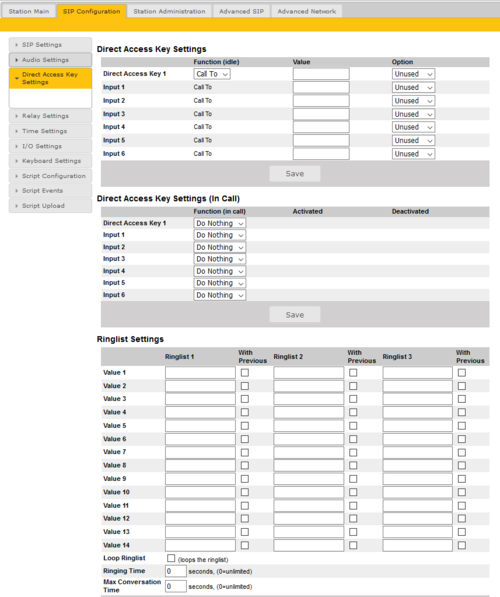
Select SIP Configuration > Direct Access Key Settings to access the page for configuring DAKs.
Note: The availability of these parameters and the number of keys depend on the Turbine station type selected under Main Settings.
Direct Access Key Settings:
- Direct Access Key 1 - Direct Access Key 10: Enter the number to call when a DAK key is pressed.
- Input 1 - Input 6: Enter the number to call when the input is activated.
Direct Access Key Settings (In Call):
- Direct Access Key 1 - Direct Access Key 10: Select what action to execute if the DAK key is pressed while in a conversation.
- Input 1 - Input 6: Select what action to execute if the input is activated while in a conversation.
- Options are:
- End Call
- Do Nothing (Default)
- Send Text
- Send DTMF
Ring List Settings
Log on to the web interface of the station that will be making the call to configure the ringlist of the stations that should be called.
To configure a ringlist:
- Select SIP Configuration > Direct Access Key Settings
There are variants of ringlists that can be set such as ringing time intervals, loopback, and ringing together with previous stations.
Note: Some telephone gateways accept a call immediately on incoming calls – even before the call has been accepted by the user (telephone). This terminates the ringlist sequence and any subsequent numbers in the ringlist will never be called. This is solved by placing the gateway number at the end of the ringlist and disabling the “With Previous” option. Ringlists that include an auto-accepting gateway will never loop back.
Ring List with Ringing Time Intervals
By using the Ring List, an unattended call can be forwarded to another station after a preset time. The call loop can include several stations.
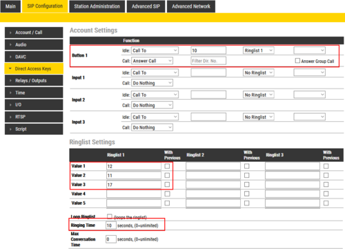
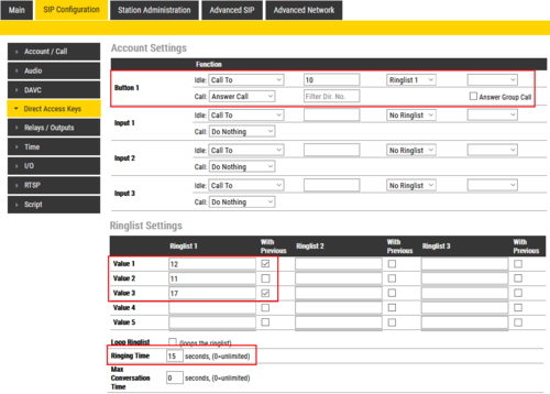
Example: When the call button is pressed, the call goes to station number 10. If not answered within 10 seconds, the call will be forwarded to station number 12. If not answered, the call will be routed to 11, and finally to station number 17.
Configuration:
Ring List with Loopback
When using the Ring List, an unattended call can be go through a call loop a preset number of times.
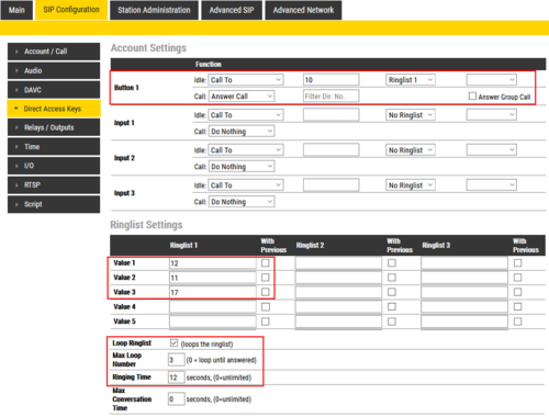
Example: When the call button is pressed, the call goes to station number 10. If not answered within 12 seconds, the call will be forwarded to station number 12. If not answered, the call will be routed to 11, and finally to station number 17.
Now the call is looped back to station number 10, repeating the same call pattern 3 times.
Configuration:
Ring List with Previous Station
By using the With Previous flag in the Ring List, one can call several stations in parallel. When one of the stations answers, it will stop ringing in the other(s).
Example: When the call button is pressed, the call goes to station number 10 and 12 in parallel. If not answered within 15 seconds, the call will be forwarded to station number 11 and 17.
Configuration:
Relay Settings
To configure the relays:
- Select SIP Configuration > Relay Settings
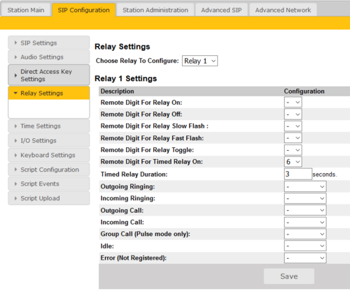
- Relay Settings: Select Relay 1, Relay 2, Relay 3 (TA-10 Relay Unit) or Relay 4 (TA-10 Relay Unit) from the drop-downbox.
- Timed Relay Duration: This parameter determines how long the relay should stay ON in seconds when triggered by the Remote Digit For Timed Relay ON event.
Note: How many relays that are actually available depends on what Turbine station model is being used.
Time Settings
- Select SIP Configuration > Time Settings from the menu
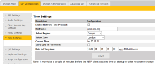
Time Settings: You can enable Network Time Protocol, select the time zone and set the hostname or the IP address of the NTP server.
I/O Settings
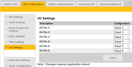
These settings let you choose if an I/O should be used as an Input or as an Output. By default all I/O's are set as Inputs.
- Select SIP Configuration > I/O Settings from the menu
- Select either Input or Output options from the drop-down box for I/O Pins 1 to 6.
Virtual I/O using Scripts
Virtual I/O is a feature for activating scripts on station events. The supported script languages are Lua and other shell scripting languages. With an I/O Extension license, the Virtual I/O feature is enabled and a station can be triggered, e.g. by DTMF to execute scripts towards other systems, e.g. access control systems. These scripts can be uploaded and configured via the menu options:
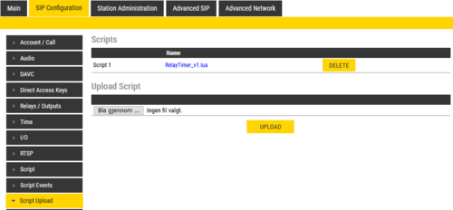
- Script Upload
- Script Configuration
- Script Events
Script Upload
To start with, a script should be uploaded to the station. It is possible to download scripts from the station by clicking its Name. Scripts are kept during a software upgrade process.
- Select SIP Configuration > Script Upload
- Upload Script: Click Browse to upload the desired script
Script Configuration
- Select SIP Configuration > Script Configuration
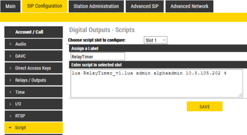
After uploading a script the user must configure a script slot (Slot 1 - Slot 10). First, assign a logical name to the script in the Assign a Label field. Then, enter the script to activate and add parameters in the text field under Enter script in selected slot (note that shell scripts don’t need to be uploaded as it is possible to write the script direclty in the text field). Lua scripts have the followings syntax:
lua <scriptname> <parameter1> <parameter2> <parameter3> ....
Shell scripts follow the same syntax, but starts with sh:
sh <scriptname> <parameter1> <parameter2> <parameter3> ...
The uploaded scripts should clearly state which parameters are needed in the beginning of the file.
The example shown in the screenshot above has 4 parameters: username, password, the IP address of the TruPortal device, and door number to activate. The parameter values in the example are:
- Username = admin
- Password = alphaadmin
- IP address = 10.5.105.202
- Door number = 4
Script Events
- Select SIP Configuration > Script Events
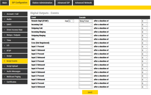
After a script slot has been created, you need to configure which Event that should Execute the script.
In the example below, the script "Grant Door Access" will be executed when the station received DTMF digit #6 from the remote station:

