Unlock two doors using one station: Difference between revisions
From Zenitel Wiki
(Created page with "It is possible to use a single Turbine IP station to unlock two different doors (or gates) independently of each other. Each door has a single access digit that unlocks only t...") |
|||
| Line 25: | Line 25: | ||
[[File:Unlock two doors 1.png|thumb|left|500px]] | [[File:Unlock two doors 1.png|thumb|left|500px]] | ||
<br style="clear:both;" /> | <br style="clear:both;" /> | ||
==Turbine Setup== | |||
All IP stations require a two-part setup procedure – one part in the station and the other using the AlphaPro programming tool. It is assumed here that the station is already configured and operational with the AlphaCom system. What follows are the changes needed to allow relay and I/O functions. | |||
===StationWeb=== | |||
Login to the Turbine station and select '''Advanced AlphaCom'''. Select '''I/O Settings''' and in the line titled '''I/O Pin 2''' choose '''Output 2''' in the dropdown '''Configuration''' box. Next select '''Save'''. | |||
Revision as of 11:55, 7 April 2016
It is possible to use a single Turbine IP station to unlock two different doors (or gates) independently of each other. Each door has a single access digit that unlocks only that door.
In the manner described in this article, the Turbine has a potential to control seven devices using the single built-in relay and six I/O ports. For practicality and clarity, the examples show only two devices being controlled – one with the built-in relay and one with an I/O port. For control of more devices, simply expand the setup and programming to the other I/O ports. If using the Turbine extended, there are two relays + 6 I/O's available.
Hardware
An IP Turbine and at least one external relay (such as the Zenitel Multi-Relay Board (MRB)) is required. A third party relay board must be able to accept a logical input (5vdc or 0vdc) to trigger the relay. A master station with LCD screen and dialing pad is also be required.
For testing, a multi-meter that can read both Ohms and Volts (VDC) is needed.
Connections
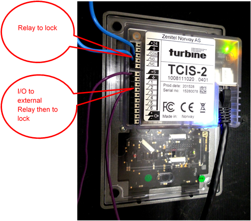
To use the Turbine inbuilt relay, connect the first set of lock control wires to the Common and NO (Normally Open) connection points (Note: Ground is NOT Common). The numbered connection ports (1-6) on the back of the Turbine correspond to I/O ports 1-6. To use any of the Turbines six I/O ports, connect the external relay board trigger wires to the connectors labeled +5 and one of the labeled connectors 1, 2,3,4,5 or 6, based on which output port will be used. Output wires from the relay board run on to the second lock control device. See also Turbine Compact and MRBD.
Note: +5 is used as the common so that when the output is active
it will be +5VDC and when not active the output will be 0VDC.

Additional note: It is assumed here that the external relay logical
trigger will be 1 (ON) to close the contact. Rarely, some external
relays may expect 0VDC to trigger. If this condition is encountered,
move the lead from +5VDC to 0VDC. This will cause the normal state
of the I/O port to be +5VDC and the active state to be 0VDC in effect
reversing normal logic controls.
This example uses the built-in relay and I/O port 2:
Turbine Setup
All IP stations require a two-part setup procedure – one part in the station and the other using the AlphaPro programming tool. It is assumed here that the station is already configured and operational with the AlphaCom system. What follows are the changes needed to allow relay and I/O functions.
StationWeb
Login to the Turbine station and select Advanced AlphaCom. Select I/O Settings and in the line titled I/O Pin 2 choose Output 2 in the dropdown Configuration box. Next select Save.

