|
|
| Line 1: |
Line 1: |
|
| |
| {|border="1" | | {|border="1" |
| |width="250px"| | | |width="250px"| |
| Line 8: |
Line 7: |
| |} | | |} |
|
| |
|
| [[File:TCIS Mounting-1.PNG|thumb|700px|left]]
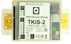
| | [[File:TKIS-2_2.png|thumb|300px|left|TKIS-2]] |
| [[File:TKIS-2.PNG|thumb|300px|left|TKIS-2]] | |
| <br style="clear:both;" />
| |
| | |
| =TCIS Compact Station Dimensions=
| |
| [[File:TCAS Dimmensions-2.PNG|200px|''TCIS Compact Station - Front view'']]
| |
| [[File:TCIS Dimensions 1.PNG|200px|''TCIS Compact Station - Side view'']]
| |
| | |
| <br style="clear:both;" /> | | <br style="clear:both;" /> |
|
| |
|
| Line 21: |
Line 13: |
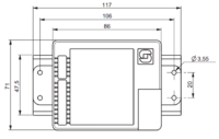
| [[File:TKIS-2-Dimensions.PNG|200px|''TKIS-2 -Front view'']] | | [[File:TKIS-2-Dimensions.PNG|200px|''TKIS-2 -Front view'']] |
| [[File:TKIS-2-Dimensions1.PNG|200px|''TKIS-2 -Side view'']] | | [[File:TKIS-2-Dimensions1.PNG|200px|''TKIS-2 -Side view'']] |
|
| |
| =Onwall Surface Mounting=
| |
| ==On-Wall Surface Mount Back Box - TA-1==
| |
| Mounting holes are to be drilled as shown.
| |
|
| |
| Max. recommended screw diameter: ISO M6 or ANSI 1/4". Screw length must be greater than 25 mm or 1". A4 stainless steel socket head screws/bolts are recommended. Max. recommended screw head diameter: 9.5 mm or 3/8".
| |
|
| |
| Optional nylon washers for extra protection against corrosive effects between surfaces are provided. They should be placed at the bottom of the mounting holes.
| |
| Grommets and an M20 cable gland are provided.
| |
|
| |
| [[File:TCAS Mounting-1.PNG|500px|''Onwall backbox Mounting holes - Side view'']]
| |
| [[File:TCAS Mounting-2.PNG|200px|''Onwall backbox - Side view'']]
| |
|
| |
| <br style="clear:both;" />
| |
|
| |
| ==On-Wall Surface Mounting Procedure==
| |
|
| |
| [[File:TCAS Mounting-3.PNG|''Onwall mounting - exploded view'']]
| |
|
| |
| :1. Mount the back box onto the wall
| |
| :2. Fit the gasket onto the back box with the ridged side facing down
| |
| ::–Plug the Ethernet cable into the RJ-45 port on the station
| |
| :3. Mount the Turbine station onto the back box with the M5 fasteners provided
| |
|
| |
| '''Note!''' Use the grommets and M20 cable gland provided for the cable holes on the back box
| |
|
| |
| =Flush Mounting=
| |
| ==Flush Mount 2-Gang Back Box - TA-3==
| |
| [[File:TCAS Mounting-4.PNG|''TA2 2-Gang backbox dimensions'']]
| |
|
| |
| '''Note!''' It is recommended to utilize back boxes with weep holes at the bottom
| |
|
| |
| <br style="clear:both;" />
| |
|
| |
| ==Flush Mount Bracket - TA-5==
| |
| Fits US 2-GANG electrical boxes. Recommended screw diameter: up to M4 (5/32"). Use screw recommended by back box manufacurer.
| |
|
| |
| [[File:TCAS Mounting-5.PNG|''TA-5 Mounting Bracket dimensions'']]
| |
| [[File:TCAS Mounting-6.PNG|''TA-5 Mounting Bracket'']]
| |
|
| |
| '''Note!''' The TA-5 Bracket is mandatory for flush mounting.
| |
|
| |
| <br style="clear:both;" />
| |
|
| |
| ==Flush Mounting Procedure==
| |
| [[File:TCAS Mounting-7.png]]
| |
|
| |
| :1. Mount the 2-gang back box into the wall
| |
| :2. Mount the bracket onto the back box
| |
| :3. Fit the gasket onto the bracket with the ridged side facing down
| |
| ::–Plug the Ethernet cable into the RJ-45 port on the station
| |
| :4. Mount the Turbine station onto the bracket with the M5 fasteners provided
| |
|
| |
|
| [[Category: Turbine]] | | [[Category: Turbine]] |


