|
|
| (3 intermediate revisions by the same user not shown) |
| Line 1: |
Line 1: |
| {{APS}} | | {{APS}} |
| {|border="1"
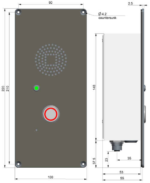
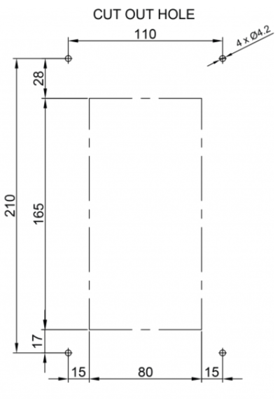
| | The ECP-AA1 is flush-mounted using 4 screw of type: |
| |width="250px"|
| | * M4x16 DIN 7991 A4 - Flat Head Socket Cap Screw, Stainless Steel A4 DIN7991 |
| |width="250px"|'''Dimensions (WxHxD)'''
| | * Length as required |
| |width="150px"|'''Weight'''
| |
| |-
| |
| |TCIS || 180 x 120 x 70 mm || 0.8 kg*
| |
| |-
| |
| |TCIS after flushmount || 180 x 120 x 20 mm ||
| |
| |-
| |
| |TCIS with onwall box || 180 x 120 x 82 mm ||
| |
| |-
| |
| |}
| |
|
| |
|
| *) TCIS-2 weight: 1.0 kg
| | [[File:ECP-AA1 Dimensions.png|500px|'ECP-AA1 - Front and side view'']] |
| | | [[File:CutOut.png|400px|''Cut Out'']] |
| =TCIS Compact Station Dimensions=
| |
| [[File:TCAS Dimmensions-2.PNG|200px|''TCIS Compact Station - Front view'']] | |
| [[File:TCIS Dimensions 1.PNG|200px|''TCIS Compact Station - Side view'']] | |
| | |
| <br style="clear:both;" />
| |
| | |
| =Flush Mounting=
| |
| ==Flush Mount 2-Gang Back Box - TA-2==
| |
| [[File:TA-2 dimensions.PNG|''TA2 2-Gang backbox dimensions'']]
| |
| | |
| '''Note!''' It is recommended to utilize back boxes with weep holes at the bottom
| |
| | |
| <br style="clear:both;" />
| |
| | |
| ==Flush Mount Bracket - TA-5==
| |
| Fits US 2-GANG electrical boxes. Recommended screw diameter: up to M4 (5/32"). Use screw recommended by back box manufacurer.
| |
| | |
| [[File:TCAS Mounting-5.PNG|''TA-5 Mounting Bracket dimensions'']]
| |
| [[File:TCAS Mounting-6.PNG|''TA-5 Mounting Bracket'']]
| |
| | |
| '''Note!''' The TA-5 Bracket is mandatory for flush mounting.
| |
|
| |
|
| <br style="clear:both;" /> | | <br style="clear:both;" /> |
|
| |
|
| ==Flush Mounting Procedure==
| |
| [[File:TCIS Flush Mounting.PNG]]
| |
|
| |
| :1. Mount the 2-gang back box into the wall
| |
| :2. Mount the bracket onto the back box
| |
| :3. Fit the gasket onto the bracket with the ridged side facing down
| |
| ::–Plug the Ethernet cable into the RJ-45 port on the station
| |
| :4. Mount the Turbine station onto the bracket with the M5 fasteners provided
| |
|
| |
| '''Ensure the station is mounted vertically with the microphone aperture facing down'''
| |
|
| |
|
| '''Ensure there is enough clearance under the station so that the microphone aperture is not smothered'''
| |
|
| |
|
| [[Category: Turbine Dimensions & Mounting Instructions]] | | [[Category: Turbine Dimensions & Mounting Instructions]] |


