MRBD - Relay Board: Difference between revisions
From Zenitel Wiki
| (16 intermediate revisions by 2 users not shown) | |||
| Line 1: | Line 1: | ||
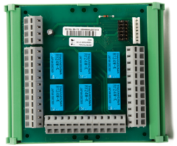
[[Image: | [[Image:1009970200.PNG|thumb|250px|The MRBD board - 1009970200]] | ||
==Highlights== | |||
* Equipped with 6 dual changeover relays and relay drivers | |||
== | |||
* Equipped with 6 relays | |||
* Powered by +24 VDC | * Powered by +24 VDC | ||
* Connector for 6 RCOs + 2 GND reference signals | * Connector for 6 RCOs + 2 GND reference signals | ||
* Connects to the AlphaCom Subscriber Connection Board through a 1:1 cable | * Connects to the AlphaCom Subscriber Connection Board through a 1:1 cable | ||
* Fastens onto mounting rail in AlphaCom exchange | * Fastens onto mounting rail in AlphaCom exchange | ||
* Relay switching capacity: 125VDC/AC, 1.25A. | |||
** 1,25A is maximum carrying current, maximum switching current at 125VAC is 0,5A. (approx. 60W). | |||
== | ==Additional Documentation== | ||
* [http://www.zenitel.com/product/mrbd Additional Documentation on Zenitel.com] | |||
== Connectors and Switches == | ==Connectors and Switches== | ||
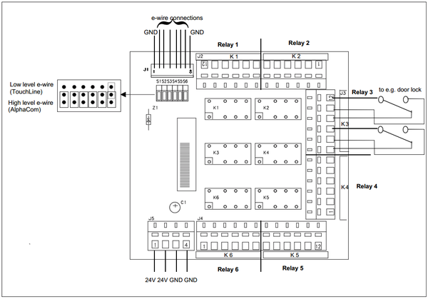
[[image:MRBD-1.PNG|thumb|left|600px|Connectors and switches on MRBD board]] | [[image:MRBD-1.PNG|thumb|left|600px|Connectors and switches on MRBD board]] | ||
<br style="clear:both;" /> | <br style="clear:both;" /> | ||
| Line 48: | Line 19: | ||
The jumpers S1-S6 determine if the RCO should be activated by a high or low level. High level is used in AlphaCom system, while low level was used in the previous TouchLine generation of intercom system. | The jumpers S1-S6 determine if the RCO should be activated by a high or low level. High level is used in AlphaCom system, while low level was used in the previous TouchLine generation of intercom system. | ||
== Connections == | ==Connections== | ||
=== AlphaCom XE7 === | ===AlphaCom XE7=== | ||
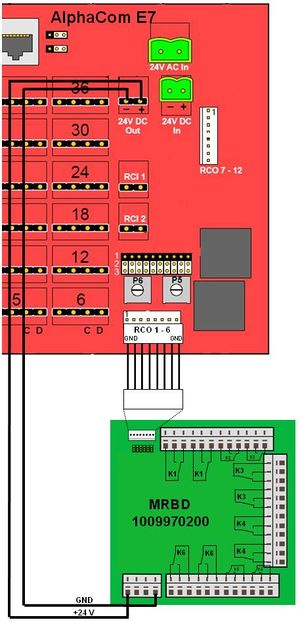
In the XE7 the cable is connected to the 8-pin pinheader labeled '''RCO 1-6''' or '''RCO 7-12'''. | In the XE7 the cable is connected to the 8-pin pinheader labeled '''RCO 1-6''' or '''RCO 7-12'''. | ||
| Line 57: | Line 28: | ||
<br style="clear:both;" /> | <br style="clear:both;" /> | ||
=== AlphaCom XE20/26 === | ===AlphaCom XE20/26=== | ||
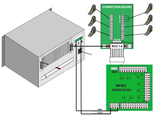
[[File:RCO XE20.PNG|thumb|500px|left|Connection of MRBD in an AlphaCom XE20]] | [[File:RCO XE20.PNG|thumb|500px|left|Connection of MRBD in an AlphaCom XE20]] | ||
| Line 66: | Line 37: | ||
==Related Articles== | ==Related Articles== | ||
*[[ | *[[Adding additional relay(s) to a Zenitel IP Device]] | ||
[[Category:Additional equipment]] | [[Category:Additional equipment]] | ||
Latest revision as of 15:12, 23 June 2023
Highlights
- Equipped with 6 dual changeover relays and relay drivers
- Powered by +24 VDC
- Connector for 6 RCOs + 2 GND reference signals
- Connects to the AlphaCom Subscriber Connection Board through a 1:1 cable
- Fastens onto mounting rail in AlphaCom exchange
- Relay switching capacity: 125VDC/AC, 1.25A.
- 1,25A is maximum carrying current, maximum switching current at 125VAC is 0,5A. (approx. 60W).
Additional Documentation
Connectors and Switches
The jumpers S1-S6 determine if the RCO should be activated by a high or low level. High level is used in AlphaCom system, while low level was used in the previous TouchLine generation of intercom system.
Connections
AlphaCom XE7
In the XE7 the cable is connected to the 8-pin pinheader labeled RCO 1-6 or RCO 7-12.
- An ASLT board in board position 1 is required to operate RCO 1 - 6.
- An ASLT board in board position 2 is required to operate RCO 7 - 12.
AlphaCom XE20/26
In an AlphaCom XE26 the 24VDC power is provided by the Power Distribution Board PDB.


