IP Substation Board Connection: Difference between revisions
From Zenitel Wiki
No edit summary |
No edit summary |
||
| Line 7: | Line 7: | ||
|width="300pt"|RJ45 connector for LAN connection. | |width="300pt"|RJ45 connector for LAN connection. | ||
|- | |- | ||
| colspan="2" | The station can be powered from this connection if the line supports Power over Ethernet. | | colspan="2" | The station can be powered from this connection if the line supports Power over Ethernet (PoE). | ||
|- | |- | ||
| colspan="2" | | | colspan="2" | | ||
Revision as of 10:03, 1 April 2008
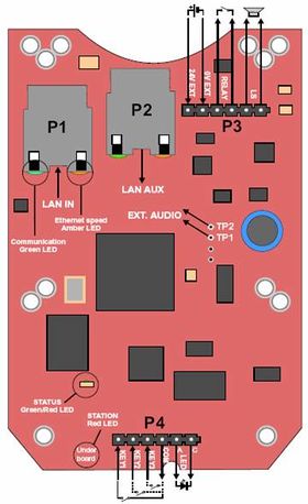
There are four connectors on the IP substation board, P1-P4.
| P1: | RJ45 connector for LAN connection. |
| The station can be powered from this connection if the line supports Power over Ethernet (PoE). | |
| P2: | RJ45 connector for auxiliary LAN equipment like TV camera, PC or a second IP station. |
| This port has not an individual IP address or power for aux equipment. | |
| P3: | 6-pin plug-on screw terminal for external connections. |
| Pin 1/2: | Connect 24 VDC for station power if power is not distributed via LAN. Pin 1 is positive. |
| Pin 3/4: | Internal NO (Normal Open) relay contact for door lock control etc. |
| Pin 5/6: | Normally connected to station loudspeaker. May be used for 16-20 ohm/2 W external loudspeaker in parallel. |
| P4: | 6-pin plug-on screw terminal for internal connections. |
| Pin 1/4: | Call button no. 1. |
| Pin 2/4: | Call button no. 2 if included |
| Pin 3/4: | Call button no. 3 if included |
| Pin 5/6: | Station LED for call and message info. |
| TP1/2: | Optional external audio output. |
| This is a 0 dB, 600 ohm balanced output for connection to a power amplifier. Note that the amplifier input MUST HAVE AN INSULATED INPUT (trafo, capacitors, etc.). | |

