Turbine Extended Board Connectors: Difference between revisions
From Zenitel Wiki
| Line 1: | Line 1: | ||
=PCB - Front= | ==PCB - Front== | ||
[[File:TFIE Connections.PNG|500px]] | [[File:TFIE Connections.PNG|500px]] | ||
<br style="clear:both;" /> | <br style="clear:both;" /> | ||
=== P1 & P2: RJ45 PoE port for 10/100 Mbit Ethernet connection === | |||
:The station can be powered from this port if the line supports Power over Ethernet (PoE). | :The station can be powered from this port if the line supports Power over Ethernet (PoE). | ||
| Line 10: | Line 10: | ||
<br style="clear:both;" /> | <br style="clear:both;" /> | ||
=== P3: Secondary Power; 24-48VDC === | |||
=== P4: 10-pin plug-on terminal for external connections === | |||
[[File:TCIS Connections 6.PNG|thumb|130px|left]] | [[File:TCIS Connections 6.PNG|thumb|130px|left]] | ||
| Line 30: | Line 30: | ||
*Output ratings: 12mA as LED drivers | *Output ratings: 12mA as LED drivers | ||
=== P5: 6-pin plug-on terminal for external connections === | |||
[[File:TFIE Connections 1.PNG|thumb|left|500px]] | [[File:TFIE Connections 1.PNG|thumb|left|500px]] | ||
:Pin 1 COM relay 1 (Common) | :Pin 1 COM relay 1 (Common) | ||
| Line 44: | Line 44: | ||
'''Note!''' In AlphaCom, relay 1 is configured as output 7, and Relay 2 is configured as output 8! | '''Note!''' In AlphaCom, relay 1 is configured as output 7, and Relay 2 is configured as output 8! | ||
=== P6: Loudspeaker & Electret microphone === | |||
[[File:TCIS Connections 7.PNG|thumb|500px|left]] | [[File:TCIS Connections 7.PNG|thumb|500px|left]] | ||
:Pin 1 10W Speaker amplifier + | :Pin 1 10W Speaker amplifier + | ||
| Line 53: | Line 53: | ||
<br style="clear:both;" /> | <br style="clear:both;" /> | ||
=== J2: [[TA-10|Turbine Relay Module - TA-10]] === | |||
=== J8: Headset/Handset connector === | |||
:Pin 1 Offhook | :Pin 1 Offhook | ||
:Pin 2 GND | :Pin 2 GND | ||
Revision as of 11:06, 28 November 2017
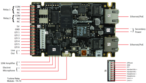
PCB - Front
P1 & P2: RJ45 PoE port for 10/100 Mbit Ethernet connection
- The station can be powered from this port if the line supports Power over Ethernet (PoE).
P3: Secondary Power; 24-48VDC
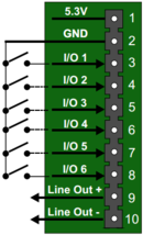
P4: 10-pin plug-on terminal for external connections
- Pin 1 5.3V
- Pin 2 GND
- Pin 3 Button Input or LED Driver
- Pin 4 Button Input or LED Driver
- Pin 5 Button Input or LED Driver
- Pin 6 Button Input or LED Driver
- Pin 7 Button Input or LED Driver
- Pin 8 Button Input or LED Driver
- Pin 9 600 ohm balanced line out +
- Pin 10 600 ohm balanced line out -
- Output ratings: 12mA as LED drivers
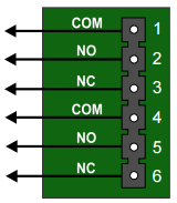
P5: 6-pin plug-on terminal for external connections
- Pin 1 COM relay 1 (Common)
- Pin 2 NO relay 1 (Normal Open)
- Pin 3 NC relay 1 (Normal Closed)
- Pin 4 COM relay 2(Common)
- Pin 5 NO relay 2 (Normal Open)
- Pin 6 NC relay 2 (Normal Closed)
- Relay switching capacity: Max. 60 watt (Max voltage: 250VAC/220VDC. Max current: 2A)
Note! In AlphaCom, relay 1 is configured as output 7, and Relay 2 is configured as output 8!
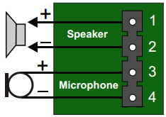
P6: Loudspeaker & Electret microphone
- Pin 1 10W Speaker amplifier +
- Pin 2 10W Speaker amplifier -
- Pin 3 Electret Microphone +
- Pin 4 Electret Microphone -
J2: Turbine Relay Module - TA-10
J8: Headset/Handset connector
- Pin 1 Offhook
- Pin 2 GND
- Pin 3 PTT
- Pin 4 Handset Mic Positive
- Pin 5 Handset Mic Negative
- Pin 6 Headphone Positive
- Pin 7 Headphone Negative
- Pin 8 Line In Positive
- Pin 9 Line In Negative


