INCA Video Doorstation Board Connectors: Difference between revisions
From Zenitel Wiki
| Line 45: | Line 45: | ||
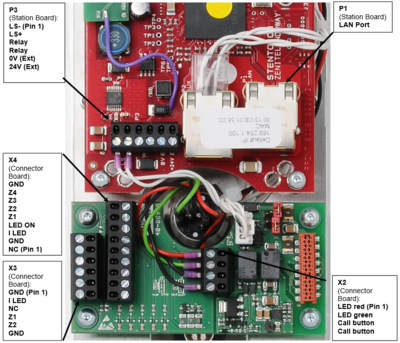
===Hardware version 0.2/0.3/1.0=== | ===Hardware version 0.2/0.3/1.0=== | ||
[[File:ConnectorsCP 2.PNG]] | [[File:ConnectorsCP 2.PNG|400px]] | ||
<br style="clear:both;" /> | <br style="clear:both;" /> | ||
'''P1:'''<br> | |||
: LAN Port | |||
'''P3:'''<br> | |||
: 1&2: Loudspeaker 4ohm/2W (already connected) | |||
: 3&4: NO Relay - Potential free relay contact, max 1A/24V | |||
: 5: 0V* | |||
: 6: 24V* | |||
*External power supply, 21-27VDC/0.5A. Attention! '''Not''' simultaneously with PoE! | *External power supply, 21-27VDC/0.5A. Attention! '''Not''' simultaneously with PoE! | ||
'''X2:'''<br> | |||
Call Button (Board version 0.2): | Call Button (Board version 0.2): | ||
# RT (for red LED (red cable)) | |||
# GR (for green LED (green cable)) | |||
# SW (closer (button)) | |||
# SW (closer (button)) | |||
'''X3:'''<br> | |||
Button Module 2T (Board version 0.2): | Button Module 2T (Board version 0.2): | ||
# GND (ground for illumination) | |||
# I_LED (background illumination (+5V)) | |||
# NC | |||
# Z1 (first button) DAK2 | |||
# Z2 (second button) DAK3 | |||
# GND (reference point buttons) | |||
'''X4:'''<br> | |||
Button Module 4T (Board version 0.2): | Button Module 4T (Board version 0.2): | ||
# NC | |||
# GND (NC) | |||
# I_LED (background illumination) | |||
# LED_ON (grounding for illumination) | |||
# Z1 (1st button) DAK4 | |||
# Z2 (2nd button) DAK5 | |||
# Z3 (3rd button) DAK6 | |||
# Z4 (4th button) DAK7 | |||
# "GND" (reference point buttons) | |||
Revision as of 12:19, 25 October 2016
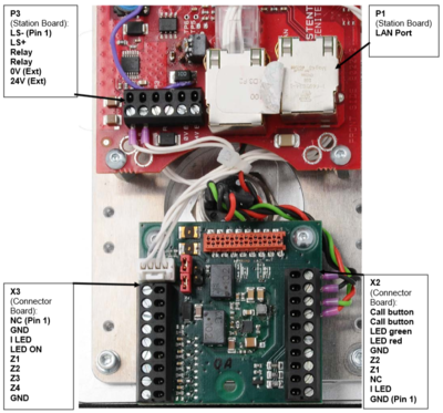
Hardware version 0.1
P1:
- LAN Port
P3:
- 1&2: Loudspeaker 4ohm/2W (already connected)
- 3&4: NO Relay - Potential free relay contact, max 1A/24V
- 5: 0V*
- 6: 24V*
*External power supply, 21-27VDC/0.5A. Attention! Not simultaneously with PoE!
X2:
Button Module 2B:
- GND (ground for illumination)
- I_LED (background illumination (+5V))
- NC
- Z1 (first button) DAK2
- Z2 (second button) DAK3
- GND (reference point buttons)
Call Button (Board version 0.1):
- 7: RT (for red LED (red cable))
- 8: GR (for green LED (green cable))
- 9: SW (closer (button))
- 10: SW (closer (button))
X3:
Button Module 4T:
- NC
- GND (NC)
- I_LED (background illumination)
- LED_ON (grounding for illumination)
- Z1 (1st button) DAK4
- Z2 (2nd button) DAK5
- Z3 (3rd button) DAK6
- Z4 (4th button) DAK7
- "GND" (reference point buttons)
Hardware version 0.2/0.3/1.0
P1:
- LAN Port
P3:
- 1&2: Loudspeaker 4ohm/2W (already connected)
- 3&4: NO Relay - Potential free relay contact, max 1A/24V
- 5: 0V*
- 6: 24V*
*External power supply, 21-27VDC/0.5A. Attention! Not simultaneously with PoE!
X2:
Call Button (Board version 0.2):
- RT (for red LED (red cable))
- GR (for green LED (green cable))
- SW (closer (button))
- SW (closer (button))
X3:
Button Module 2T (Board version 0.2):
- GND (ground for illumination)
- I_LED (background illumination (+5V))
- NC
- Z1 (first button) DAK2
- Z2 (second button) DAK3
- GND (reference point buttons)
X4:
Button Module 4T (Board version 0.2):
- NC
- GND (NC)
- I_LED (background illumination)
- LED_ON (grounding for illumination)
- Z1 (1st button) DAK4
- Z2 (2nd button) DAK5
- Z3 (3rd button) DAK6
- Z4 (4th button) DAK7
- "GND" (reference point buttons)


