Tamper switch: Difference between revisions
From Zenitel Wiki
No edit summary |
No edit summary |
||
| Line 3: | Line 3: | ||
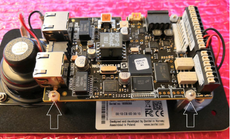
'''Step 1:''' Remove the two nylon nuts shown below | '''Step 1:''' Remove the two nylon nuts shown below | ||
[[File:Tamper1.png|thumb|left]] | [[File:Tamper1.png|500px|thumb|left]] | ||
<br style="clear:both;" /> | <br style="clear:both;" /> | ||
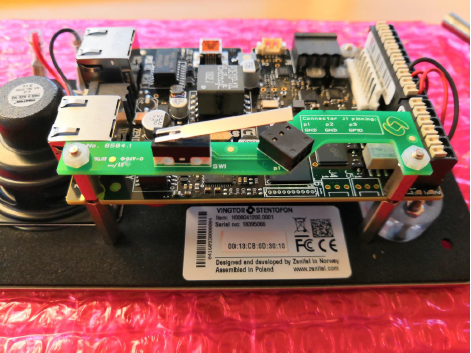
'''Step 2:''' Attach the supplied spacers | '''Step 2:''' Attach the supplied spacers | ||
[[File:Tamper2.png|thumb|left]] | [[File:Tamper2.png|500px|thumb|left]] | ||
<br style="clear:both;" /> | <br style="clear:both;" /> | ||
'''Step 3:''' Mount the tamper switch board | '''Step 3:''' Mount the tamper switch board | ||
[[File:Tamper3.png|thumb|left]] | [[File:Tamper3.png|500px|thumb|left]] | ||
<br style="clear:both;" /> | <br style="clear:both;" /> | ||
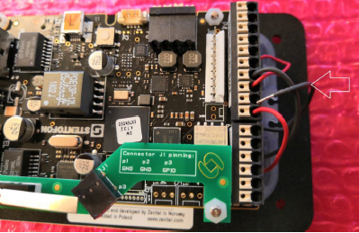
'''Step 4:''' Move the button GND wire from the the TKIE board to the tamper switch board | '''Step 4:''' Move the button GND wire from the the TKIE board to the tamper switch board | ||
[[File:Tamper4.png|thumb|left]] | [[File:Tamper4.png|500px|thumb|left]] | ||
<br style="clear:both;" /> | <br style="clear:both;" /> | ||
[[File:Tamper5.png|thumb|left]] | [[File:Tamper5.png|500px|thumb|left]] | ||
<br style="clear:both;" /> | <br style="clear:both;" /> | ||
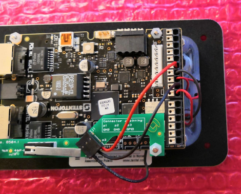
'''Step 5:''' Use the supplied wires to connect GND and Input 3 as shown below | '''Step 5:''' Use the supplied wires to connect GND and Input 3 as shown below | ||
[[File:Tamper6.png|thumb|left]] | [[File:Tamper6.png|500px|thumb|left]] | ||
<br style="clear:both;" /> | <br style="clear:both;" /> | ||
[[Category: Turbine Backboxes and accessories]] | [[Category: Turbine Backboxes and accessories]] | ||
Revision as of 14:03, 13 March 2020
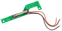
Assembly instruction on Tamper Switch for IP Vandal Resistant Substation TKIE
Step 1: Remove the two nylon nuts shown below
Step 2: Attach the supplied spacers
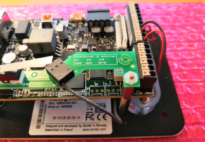
Step 3: Mount the tamper switch board
Step 4: Move the button GND wire from the the TKIE board to the tamper switch board
Step 5: Use the supplied wires to connect GND and Input 3 as shown below


