|
|
| Line 6: |
Line 6: |
|
| |
|
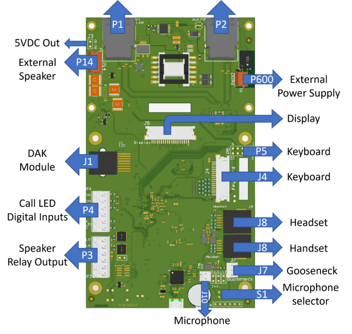
| [[File:IPFlushMasterKitPCB2.png|700px|right]] | | [[File:IPFlushMasterKitPCB2.png|700px|right]] |
|
| |
| ====P1 - LAN port & P2 AUX port====
| |
| <u>'''P1:'''</u>
| |
|
| |
| LAN connector for 10/100 Mbit Ethernet connection. The station can be powered from this connection if the line supports Power over Ethernet (PoE).
| |
|
| |
| The connector has two LEDs in front where the right (R) LED indicates Ethernet speed and the left (L) LED verifies Ethernet link and traffic. (L and R as seen from the connector side)
| |
|
| |
| <u>'''P2:'''</u>
| |
|
| |
| RJ45 connector for auxiliary equipment like IP camera, PC or a second IP station. This port does not have an individual IP address. It does not carry power for AUX equipment.
| |
| [[File:IP Master Board 1.PNG|left|thumb|200px|P1/P2]]
| |
| <br style="clear:both;" />
| |
|
| |
|
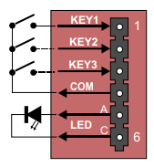
| ====P4 - Inputs and Station LED==== | | ====P4 - Inputs and Station LED==== |
Revision as of 14:11, 23 June 2023
This chapter gives details about connections and indications for:
P4 - Inputs and Station LED
6-pin plug-on screw terminal for external connections.
- Pin 1/4 Input 1
- Pin 2/4 Input 2
- Pin 3/4 Input 3
- Pin 5/6 Station LED for call message info.

|
- When "Station Type" is set as Master station in AlphaPro, the inputs are mapped as DAK 11, 12 and 13.
- When the "Station Type" is set as CRM in AlphaPro, the inputs are mapped as 251, 252 and 253.
|


